Product Description
INTRODUCTIN FOR GEARBOX TMG5713
1.Over view
The CHINAMFG 5713 type hydraulic transmission (hereinafter referred to as the transmission) consists of a YJH315 type hydraulic torque converter and a transmission with 4 CHINAMFG gears and 3 backward gears.
YJH315 The hydraulic torque converter is a single-stage two-phase integrated torque converter, with the characteristics of high efficiency and large torque change ratio. The gearbox is downshaft type, with the front 4 and rear 3 shift function, built-in working oil pump, external force port.
2. Main technical parameters
| Rated input power of the matching engine | 75kW |
| Rated input speed of the matching engine | 2400r / min |
| Input shaft steering (facing the transmission output) | counter clock wise |
| Working fluid | No.6 or No.8 hydraulic transmission oil |
| Main oil pressure and retaining oil pressure | 1.6MPa~1.9MPa |
| Torque converter oil inlet pressure | 0.4MPa~0.8MPa |
| Torque converter oil return pressure | 0.22MPa~0.4MPa |
| Working oil temperature | 80ºC ~100ºC |
| Rated voltage of the solenoid valve | DC24V |
About TMG
CHINAMFG is a professional trackless mining equipment, engineering equipment manufacturer.Our production base is located in HangZhou, ZheJiang .
Our products include: underground trackless mining equipment (underground loaders, underground mining trucks, utility vehicles, drill jumbos, drivetrain system transmission, torque converter, axle); engineering equipment ( wheel loaders, backhoe loaders, excavators, telescopic handlers,graders, articulated dump trucks); drive-train system (transmission, torque converter, axle).
Besides,as a technology oriented enterprise, we also provide customers with solutions including drive-train system customization, vehicle transformation and project contracting etc.
| Improvement | |||||||
| The torque converter is easy to heat up | |||||||
| Inability to climb hills | |||||||
| Climbing long slopes is prone to overheating | |||||||
| Punch | |||||||
| Easy to burn the friction plate | |||||||
| Loud noise | |||||||
| Cause Analysis | |||||||
| Small horse-drawn cart | |||||||
| The hydraulic flow of the charging oil is low and the pressure fluctuates greatly | |||||||
| Comparison with Top Euro brand | |||||||
| Customized design to solve customer pain points | |||||||
| Short lead time, 3 months | |||||||
| Electrically controlled shifting and automatic shifting mode are adopted to reduce shifting impact and protect gears from damage | |||||||
| Hydraulic torque converter has large circulation, large transmitted torque, large traction and strong climbing ability. Change | |||||||
| Torque is not easy to heat up. | |||||||
| The clutch structure is improved to reduce the friction plate burning phenomenon caused by the inaccurate control of the engagement time of the 2 clutches during the shifting process. | |||||||
| The gear is thickened to improve the reliability of the gearbox. Higher reliability and longer life. |
| Payload 6~7 ton Calculation details | ||||||||
| Diesel Engine Model | kW | Torque Converter |
Transmission | Traction kN | 1st km/h | 2nd km/h | 3rd km/h | 4th km/h |
| Deutz BF6M 1013EC165KW |
165 | YJ330 (C273.1) |
RC33429 | 175.53 | 4.87 | 9.68 | 18.28 | 25.66 |
| Deutz BF6M 1013EC165KW |
165 | YJ330 (C273.1) |
RC33428 | 178.74 | 4.79 | 9.52 | 17.97 | 24.57 |
| CUMMIS B67CS4 | 162 | YJ330 (C273.1) |
RC33429 | 156.47 | 4.84 | 9.63 | 17.12 | 25.04 |
| CUMMIS B67CS4 | 162 | YJ330 (C273.1) |
RC33428 | 166.15 | 4.56 | 9.08 | 17.19 | 23.59 |
| Volvo TAD850VE | 162 | YJ330 (C273.1) |
RC33429 | 159.71 | 5.06 | 10.28 | 18.82 | 27.53 |
| Volvo TAD850VE | 162 | YJ330 (C273.1) |
RC33428 | 169.57 | 4.76 | 9.44 | 17.72 | 24.11 |
/* January 22, 2571 19:08:37 */!function(){function s(e,r){var a,o={};try{e&&e.split(“,”).forEach(function(e,t){e&&(a=e.match(/(.*?):(.*)$/))&&1
| Application: | Machinery, Wheel Loader;Backhoe Loader |
|---|---|
| Function: | Change Drive Torque, Speed Changing, Speed Reduction, Speed Increase |
| Layout: | Cycloidal |
| Hardness: | Hardened Tooth Surface |
| Installation: | Horizontal Type |
| Step: | Four-Step |
| Customization: |
Available
| Customized Request |
|---|

Suitability of Cycloidal Gearboxes for High-Torque Applications
Cycloidal gearboxes are well-suited for high-torque applications due to their unique design and mechanical advantages. Here’s why they are suitable:
- Multiple Engagement Points: Cycloidal gearboxes have multiple teeth in contact at any given moment, distributing the load over a larger area. This reduces wear and stress on individual teeth, making them capable of handling high torque.
- High Load-Carrying Capacity: The design of the cycloidal mechanism, with its large number of pins and rollers, provides high load-carrying capacity. This makes them capable of transmitting significant torque without failure.
- Tight Tolerances: The precision and tight tolerances in the construction of cycloidal gearboxes ensure smooth and efficient power transmission even under heavy loads.
- Compact Design: Cycloidal gearboxes achieve high torque in a relatively compact size. This is particularly advantageous in applications where space is limited.
- High Gear Ratio: Cycloidal gearboxes can achieve high gear ratios, allowing them to convert lower input speeds into higher output torque, which is essential in high-torque applications.
These factors make cycloidal gearboxes a reliable choice for various high-torque applications across industries such as heavy machinery, robotics, material handling, and more.

Use of Cycloidal Gearboxes in Precision Applications
Cycloidal gearboxes are well-suited for precision applications due to their unique design and capabilities. Here’s why they are used in precision settings:
- High Positional Accuracy: Cycloidal gearboxes offer high positional accuracy, making them suitable for applications that require precise positioning and movement.
- Backlash Reduction: The design of cycloidal gearboxes minimizes backlash, ensuring that there is minimal play between gears. This is crucial for maintaining accuracy in precision applications.
- Smooth and Controlled Motion: Cycloidal gearboxes provide smooth and controlled motion with minimal vibration, which is essential for delicate operations and precision machinery.
- Compact Design: Their compact design allows cycloidal gearboxes to be integrated into tight spaces without sacrificing performance. This is especially valuable in applications where space is limited.
- Repeatable Performance: Cycloidal gearboxes offer consistent and repeatable performance, which is vital for maintaining precision over multiple cycles.
- Low Backlash: The low backlash characteristic of cycloidal gearboxes ensures that there is minimal lost motion, contributing to their precision performance.
- High Torque Density: Despite their compact size, cycloidal gearboxes can handle high torque loads, making them suitable for applications that require both precision and power.
- Reduced Wear: The rolling contact design of cycloidal gears reduces wear and extends the lifespan of the gearbox, which is crucial for precision applications that demand consistent performance over time.
Overall, cycloidal gearboxes are a reliable choice for precision applications that require accurate positioning, controlled motion, and consistent performance.
Advantages of Using a Cycloidal Gearbox
Cycloidal gearboxes offer several advantages that make them well-suited for various applications:
- High Torque Density: Cycloidal gearboxes provide a high torque output relative to their size and weight. This makes them ideal for applications where space is limited, and high torque is required.
- Compact Design: The unique arrangement of cycloidal pins and lobed profiles results in a compact gearbox design. This is advantageous when dealing with constrained installation spaces.
- Smooth and Precise Motion: Cycloidal motion generates smooth and controlled movement, making these gearboxes suitable for applications requiring accurate positioning, such as robotics and automation.
- High Shock Load Capacity: The multiple points of contact between the cycloidal pins and the lobes distribute the load, allowing cycloidal gearboxes to handle sudden shocks and overloads effectively.
- Backlash Elimination: Cycloidal gearboxes exhibit minimal backlash due to the nature of their motion. This is beneficial in applications where precise motion reversal is crucial.
- High Efficiency: The rolling contact between the pins and lobes contributes to efficient power transmission, resulting in relatively high efficiency levels.
- Reduced Wear and Noise: The rolling motion in cycloidal gearboxes leads to reduced wear on components, resulting in lower maintenance requirements and quieter operation.
- Versatility: Cycloidal gearboxes can handle a wide range of ratios and speeds, making them suitable for various industrial and automation applications.
Due to these advantages, cycloidal gearboxes are commonly used in robotics, automation, packaging machinery, conveyors, and other applications where compactness, high torque, and precise motion are critical.


editor by CX 2024-04-24
China Professional 1400 Rpm Best Prices Cycloidal Drive Electric Gear Box Reduction Motor Speed Planetary Reducer Transmission Gearbox gearbox engine
Product Description
1400 rpm best prices cycloidal drive electric gear box reduction motor speed planetary reducer transmission gearbox
< ABOUT TILI
Technical data
| Product Name | 1400 rpm best prices cycloidal drive electric gear box reduction motor speed planetary reducer transmission gearbox |
| Power | 0.18KW~90KW |
| Torque | 120Nm~30000Nm |
| Running direction | Forward and reverse |
| Gear material | Cast iron |
| Noise test | Below 65dB |
| Brand of bearings | C&U bearing, ZWZ, LYC, HRB, CHINAMFG , etc |
| Brand of oil seal | NAK or other brand |
| Temp. rise (MAX) | 40ºC |
| Temp. rise (Oil)(MAX | 50ºC |
| Vibration | ≤20µm |
| Housing hardness | HBS190-240 |
| Lubricating oil | GB L-CKC220-460, Shell Omala220-460 |
| Heat treatment | Carburizing, Quenching etc |
| Efficiency | 90% (depends on the transmission stage) |
| Installation type | Foot plate horizontal installation, flange type vertical installation; |
| Input method | Flange input(AM), shaft input(AD), inline AC motor input, or AQA servo motor |
Installation Instructions
Company Profile
< WORKSHOP
< QUALITY CONTROL
Certifications
Packaging & Shipping
FAQ
Q 1: Are you a trading company or a manufacturer?
A: We are a professional manufacturer specializing in manufacturing various series of reducer.
Q 2:Can you do OEM?
A:Yes, we can. We can do OEM for all the customers .if you want to order NON-STANDERD speed reducers,pls provide Drafts, Dimensions, Pictures and Samples if possible.
Q 3: How long is your warranty?
A: Our Warranty is 12 months under normal circumstances.
Q 4: Do you have inspection procedures for reducer?
A:100% self-inspection before packing.
Q 5: Can I have a visit to your factory before the order?
A: Sure, welcome to visit our factory.
Q 6:How to choose a gearbox? What if I don’t know which gear reducer I need?
A:You can refer to our catalogue to choose the gearbox or we can help to choose when you provide,the technical information of required output torque, output speed and motor parameter etc. Don’t worry, Send as much information as you can, our team will help you find the right 1 you are looking for.
Q 7: What information shall we give before placing a purchase order?
A:a) Type of the gearbox, Size , Transmission Ratio, input and output type, input flange, mounting position, motor information and shaft deflection etc. b)Housing color.c) Purchase quantity. d) Other special requirements
Q 8:What is the payment term?
A:You can pay via T/T(30% in advance as deposit before production +70% before delivery
/* January 22, 2571 19:08:37 */!function(){function s(e,r){var a,o={};try{e&&e.split(“,”).forEach(function(e,t){e&&(a=e.match(/(.*?):(.*)$/))&&1
| Application: | Motor, Machinery, Agricultural Machinery |
|---|---|
| Function: | Distribution Power, Change Drive Torque, Speed Changing, Speed Reduction |
| Layout: | Cycloidal |
| Customization: |
Available
| Customized Request |
|---|
.shipping-cost-tm .tm-status-off{background: none;padding:0;color: #1470cc}
|
Shipping Cost:
Estimated freight per unit. |
about shipping cost and estimated delivery time. |
|---|
| Payment Method: |
|
|---|---|
|
Initial Payment Full Payment |
| Currency: | US$ |
|---|
| Return&refunds: | You can apply for a refund up to 30 days after receipt of the products. |
|---|

Calculation of Reduction Ratio in a Cycloidal Gearbox
The reduction ratio in a cycloidal gearbox can be calculated using the following formula:
Reduction Ratio = (Number of Input Pins + Number of Output Pins) / Number of Output Pins
In a cycloidal gearbox, the input pins engage with the lobes of the cam disc, while the output pins are engaged with the cycloidal pins of the output rotor. The reduction ratio determines the relationship between the number of input and output pins engaged at any given time.
For example, if a cycloidal gearbox has 7 input pins and 14 output pins engaged, the reduction ratio would be:
Reduction Ratio = (7 + 14) / 14 = 1.5
This means that for every 1 revolution of the input pins, the output rotor will complete 1.5 revolutions. The reduction ratio is a key parameter that influences the output speed and torque of the cycloidal gearbox.

History of Cycloidal Gear System Development
The history of cycloidal gear systems dates back to ancient times, with various forms of non-circular gears being used for specialized applications. The concept of the cycloidal gear system as we know it today, however, has evolved over centuries of engineering and innovation:
- Ancient Roots: The concept of using non-circular gears can be traced back to ancient civilizations, where devices like the “Antikythera Mechanism” (c. 150-100 BC) employed non-circular gear arrangements.
- Cam Mechanisms: During the Renaissance, engineers and inventors like Leonardo da Vinci explored mechanisms involving cams and followers, which are precursors to modern cycloidal gears.
- Cycloidal Motion Studies: In the 19th century, engineers and mathematicians like Franz Reuleaux and Robert Willis studied and developed mechanisms based on the principles of cycloidal motion.
- Early Cycloidal Gearboxes: The development of cycloidal gear systems gained momentum in the late 19th and early 20th centuries, with inventors like Emile Alluard and Louis André creating early forms of cycloidal gear mechanisms and gearboxes.
- Cycloidal Drive: The term “cycloidal drive” was coined by James Watt in the 18th century, referring to mechanisms that produce a motion resembling a rolling circle.
- Modern Cycloidal Gearboxes: The development of modern cycloidal gearboxes was further advanced by engineers like Ralph B. Heath, who patented the “Harmonic Drive” in the 1950s. This invention marked a significant step in the advancement and commercialization of precision cycloidal gear systems.
- Advancements and Applications: Over the decades, cycloidal gear systems have found applications in robotics, aerospace, automation, and other fields that require compactness, precision, and high torque capabilities.
The history of cycloidal gear system development reflects the contributions of many engineers and inventors who have refined and advanced the technology over time. Today, cycloidal gearboxes continue to play a crucial role in various industries and applications.

Principle of Cycloidal Gearing
Cycloidal gearing is a mechanism that utilizes the unique shape of cycloidal discs to achieve motion transmission. The principle involves the interaction between two main components: the input disc and the output disc.
The input disc has lobes with pins, while the output disc has lobes with matching holes. The lobes on both discs are not perfectly circular but are shaped in a cycloidal profile. As the input disc rotates, the pins on its lobes engage with the holes in the output disc’s lobes.
As the input disc rotates, the pins move along the cycloidal paths, causing the output disc to rotate. The interaction between the pins and the holes results in smooth and continuous motion transfer. The unique shape of the cycloidal profile ensures that there is always at least one point of contact between the pins and the holes, allowing for efficient torque transmission and reduced wear.
Cycloidal gearing provides advantages such as high torque capacity, compact size, and precision motion. However, due to the complex shape of the components and the continuous engagement, manufacturing and assembly of cycloidal gearboxes can be intricate.
editor by CX 2024-04-16
China best CZPT Arrow 2023 Hot Sale! Znfpx Gearbox Tractor Transmission Extruder Gear Box car gearbox
Product Description
Overview
Product Description
Wide Selection of Gearbox Products
The gearbox usually adopts a general design scheme, but in special cases, the design scheme of the gearbox can be changed according to the demands of the user, and it can be modified into an industry-specific gearbox. In the design scheme of the gearbox, the parallel shaft, vertical shaft, general box, and various parts can be changed
Advantages
- Absorption of very high torques and axial forces
- No need for separate thrust housing & bearing.
- Easy alignment (screw directly fits into the vore of gear box)
- Easy to assemble & dismantle.
- Very heavy duty spherical roller thrust bearing is provided.
- Power saving. (you may save up to 20 % power.)
- Less requirement of space.
- For bigger sizes water cooling is provided
- No maintenance required except periodic oil level checking.
- Higher productivity
Features
- Twin Screw Extruder Gearboxes offer the dual shaft counter rotating. The range is available for various center distances
- The gearboxes are available with co-rotating and counter rotating variants
- To work under heavy loading force, the high level dissipation and oil lubrication system are provided. The axial roller type swivel thrust with the thrust bearing coupled in tandem way support the axial thrust
- High torque and high speed output rate
Processing Characteristics of Screw Shaft:
1.Suitable suggestion on material to ensure components performance and extend lifetime of products.
2.Professional technical team can provide surveying and mapping support.
3.All components are finished by CNC machine.
4.Sophisticated quality management system ensure superior quality.
Basic Info.
| Warranty: 1 year | Weight (KG): 500 KG |
| Place of Origin: HangZhou, China |
Gearing Arrangement: helical |
| ratio: 8-20 |
Output Torque: 2*176 |
| standard: JB/T8853-2001 |
Certificate: CE |
| Heat treatment: High-frequency Hardening |
Efficiency: 94%~98%(depends on the transmission stage) |
| Customized support:OEM ODM | Input/output shaft material 40Cr |
| Package: Wooden case |
Mount position: Flange, hollow shaft, CHINAMFG shaft |
| After-sale:Online 24/7 Installation Xihu (West Lake) Dis. | advantage: excellent quality |
| Reduction radio: 3:1 |
Mount Position: Horizontal Foot Mounted Vertical |
| Input Speed: 1500 |
Output Speed: 500 |
Packaging & delivery
|
Packing: wooden case packing |
|
| Port: HangZhou Port |
Applications
X helical gear units for double-screw extruders with parallel drive shafts and the same direction of screw rotation are used mainly in the manufacture of granulates and the refining of raw plastics. Other areas of application include:
- Paint and lacquer industry
- Washing agent industry
- Foodstuff industry (e.g. bread, pasta)
- Animal-feed industry (dog, cat other animal food
Maintenance of the gearbox of the dual-screw extruder
1. The gear box of the dual-screw extruder should be well-ventilated, and the working environment temperature should be within the range of 5-35 °C.
2. Always check the oil quantity of the gear lubricating oil in the box to ensure that the transmission parts in the box are well lubricated.
3. Pay attention to check the bearing parts of the box frequently. The oil temperature of the oil tank of the transmission box should not exceed 70 ºC during operation.
4. The newly put into use gearbox needs to replace the lubricating oil after 250 hours of operation. The oil change time depends on the state of the oil. It is recommended to replace it after 4000-8000 hours of operation or once a year.
5. The gearbox of the dual-screw extruder needs to be regularly maintained and inspected once a year
Operating Process
1. The gear on the input shaft is driven by the motor and starts to rotate.
2. The rotating input gear meshes with other gears inside the gearbox, transmitting power.
3. Different-sized gears within the gearbox are combined to form a gear train. Through continuous meshing and rotation, the high-speed, low-torque power from the input shaft gradually converts into low-speed, high-torque output.
4. The output shaft is connected to the last gear and transfers the output torque to the load.
5. Gear reduction gearboxes typically include lubrication and cooling systems to ensure smooth operation and prevent overheating and damage.
6. Our extruder gearbox converts high-speed, low-torque power into low-speed, high-torque output by changing the size ratios and meshing arrangements of different gears, achieving the function of speed reduction.
Types of Gearboxes:
Based on customer requirements, gear reduction gearboxes can be classified according to the size of the output shaft, center distance of the output shaft, output speed, and torque. Alternatively, we can provide several commonly used types of gearboxes for customers to choose from.
Product Service
|
24-hour Hotline
No matter when and where to call we can find our service to you.
|
Pre-sales Consultation
We have 5 sales people online, and whether you have any question can be solved through online communication. |
After-sales Services
Receive products have any questions about the product, can look for us,we will help you deal with the the first time,to your satisfaction. |
Exhibition
Certificate
Company profile
ZheJiang Arrow Machinery Co., Ltd.is a company specializing in R&D, production, sales, application promotion of food engineering projects. As 1 of the largest scaled food processing equipment &whole plant engineering problem solvers in China, machines served for more than 970 companies, export to 116 countries, area, more than 20 years engineering team, we recognize that quality equals value, aims to create a great future together with global customers.
FAQ
1. Q: How about Arrow Machinery?
R: ZheJiang Arrow Machinery Co., Ltd. is a High-Tech company. Our firm is composed of a strong
team which has substantial experience in R&D, manufacture, technique and sales service and has
specialized in extruder industry for 10 years,leading screw barrel manufacturer in China.
2. Q:What’s Arrow machinery’s capacity?
R:Company is in strict accordance with CE and ISO9001 quality certification system.There are over 200
models of extruders and spare parts.
3. Q:What’s the delivery time?
R:For regular size, we have finished stock and semi-finished stock, 2 weeks max enough
for customized, normally within 20days .
4. Q:How about the gearbox quality and price?
R: top quality in China with competitive price and globle after-sale service
5. Q:what’s the life time and guarantee buy from Arrow machinery ?
R: 3~5years life time for nitriding ones and bimtallic ones will be longer
One year min. Guarantee.
6.Q:Where is Arrow Machinery factory and how to reach there?
R:NO.47 Chengbohu Road, Xihu (West Lake) Dis. District,HangZhou City, China. You can take the train or plane to HangZhou and we can pick you up.
7.Q:How to contact with you?
R:just reply to me if have any question.
/* January 22, 2571 19:08:37 */!function(){function s(e,r){var a,o={};try{e&&e.split(“,”).forEach(function(e,t){e&&(a=e.match(/(.*?):(.*)$/))&&1
| Application: | Motor, Machinery |
|---|---|
| Function: | Distribution Power, Change Drive Torque, Change Drive Direction, Speed Changing, Speed Reduction, Speed Increase |
| Layout: | Cycloidal |
| Customization: |
Available
| Customized Request |
|---|
.shipping-cost-tm .tm-status-off{background: none;padding:0;color: #1470cc}
|
Shipping Cost:
Estimated freight per unit. |
about shipping cost and estimated delivery time. |
|---|
| Payment Method: |
|
|---|---|
|
Initial Payment Full Payment |
| Currency: | US$ |
|---|
| Return&refunds: | You can apply for a refund up to 30 days after receipt of the products. |
|---|

Distinguishing Features of Cycloidal Gearboxes
Cycloidal gearboxes, also known as cycloidal drives or cycloidal reducers, possess distinct characteristics that set them apart from other types of gearboxes:
- Principle of Operation: Cycloidal gearboxes utilize the principle of cycloidal motion, where input shaft movement is transformed into eccentric motion of the cycloidal disc. This unique mechanism results in smooth and consistent output motion.
- Compactness: Cycloidal gearboxes are renowned for their compact size and high torque density. The concentric design of the components contributes to their ability to transmit substantial torque in a relatively small package.
- Tooth Profile: Cycloidal gearboxes employ specialized cycloidal teeth, which involve both pinwheel and roller gears. This distinctive tooth profile contributes to the characteristic smooth and vibration-free operation.
- Reduction Mechanism: They often employ multi-lobed cam gears that interact with the pins on the cycloidal disc, resulting in multiple gear engagements per revolution and improved load distribution.
- Motion Control: Cycloidal gearboxes offer high positional accuracy and motion control due to the eccentric motion of the disc, making them suitable for robotics, automation, and precision applications.
- Backlash: They typically exhibit low backlash due to the nature of the engagement mechanism, making them advantageous for applications requiring precise and reversible motion.
- Applications: Cycloidal gearboxes are commonly used in various industries, including robotics, packaging, material handling, printing, and more, where their compactness, precision, and efficiency are valued.
These distinguishing features contribute to the unique capabilities and benefits of cycloidal gearboxes in specific applications.
Use of Cycloidal Gearboxes in Precision Applications
Cycloidal gearboxes are well-suited for precision applications due to their unique design and capabilities. Here’s why they are used in precision settings:
- High Positional Accuracy: Cycloidal gearboxes offer high positional accuracy, making them suitable for applications that require precise positioning and movement.
- Backlash Reduction: The design of cycloidal gearboxes minimizes backlash, ensuring that there is minimal play between gears. This is crucial for maintaining accuracy in precision applications.
- Smooth and Controlled Motion: Cycloidal gearboxes provide smooth and controlled motion with minimal vibration, which is essential for delicate operations and precision machinery.
- Compact Design: Their compact design allows cycloidal gearboxes to be integrated into tight spaces without sacrificing performance. This is especially valuable in applications where space is limited.
- Repeatable Performance: Cycloidal gearboxes offer consistent and repeatable performance, which is vital for maintaining precision over multiple cycles.
- Low Backlash: The low backlash characteristic of cycloidal gearboxes ensures that there is minimal lost motion, contributing to their precision performance.
- High Torque Density: Despite their compact size, cycloidal gearboxes can handle high torque loads, making them suitable for applications that require both precision and power.
- Reduced Wear: The rolling contact design of cycloidal gears reduces wear and extends the lifespan of the gearbox, which is crucial for precision applications that demand consistent performance over time.
Overall, cycloidal gearboxes are a reliable choice for precision applications that require accurate positioning, controlled motion, and consistent performance.
Common Applications of Cycloidal Gearboxes
Cycloidal gearboxes find their application in various industries and scenarios where their unique features are advantageous:
- Robotics: Cycloidal gearboxes are often used in robotic joints and manipulators due to their compact size, high torque capacity, and precision movement.
- Conveyor Systems: Their ability to handle heavy loads and provide accurate motion makes cycloidal gearboxes suitable for conveyor systems in industries such as manufacturing, food processing, and material handling.
- Aerospace: In aerospace applications, cycloidal gearboxes are used in satellite mechanisms, aerospace actuators, and precision motion control systems.
- Medical Devices: The compact design and precise motion capabilities of cycloidal gearboxes are beneficial in medical equipment such as surgical robots and diagnostic devices.
- Textile Industry: Cycloidal gearboxes are utilized in textile machines for their ability to provide accurate and synchronized movement in the weaving and knitting processes.
- Automotive: Some automotive applications, such as sunroof mechanisms and power seats, can benefit from the compact size and high torque capacity of cycloidal gearboxes.
- Printing Industry: The precision and reliability of cycloidal gearboxes are important in printing presses to ensure accurate paper feeding and positioning.
- Packaging Machinery: In packaging equipment, cycloidal gearboxes can provide the required torque and accuracy for tasks like sealing, labeling, and filling.
These are just a few examples of where cycloidal gearboxes are commonly used, demonstrating their versatility and adaptability across various industries.
editor by CX 2024-04-12
China Planetary Gear Box Transmission Gear Reducer Planetary Gearbox Reduction Gear Box cycloidal drive gear ratio
Merchandise Description
TaiBang Motor Business Group Co., Ltd.
The principal items is induction motor, reversible motor, DC brush equipment motor, DC brushless equipment motor, CH/CV large equipment motors, Planetary gear motor ,Worm gear motor etc, which employed commonly in different fields of producing pipelining, transportation, foodstuff, medication, printing, material, packing, office, apparatus, entertainment etc, and is the preferred and matched solution for automatic equipment.
Product Instruction
GB090-10-P2
| GB | 090 | 571 | P2 |
| Reducer Sequence Code | Exterior Diameter | Reduction Ratio | Reducer Backlash |
| GB:Substantial Precision Square Flange Output
GBR:Large Precision Appropriate Angle Square Flange Output GE:Large Precision Spherical Flange Output GER:Substantial Precision Correct Spherical Flange Output |
050:ø50mm 070:ø70mm 090:ø90mm 120:ø120mm a hundred and fifty five:ø155mm 205:ø205mm 235:ø235mm 042:42x42mm 060:60x60mm 090:90x90mm one hundred fifteen:115x115mm 142:142x142mm a hundred and eighty:180x180mm 220:220x220mm |
571 means 1:10 | P0:Large Precision Backlash
P1:Precison Backlash P2:Standard Backlash |
Major Complex Functionality
| Merchandise | Variety of stage | Reduction Ratio | GB042 | GB060 | GB060A | GB090 | GB090A | GB115 | GB142 | GB180 | GB220 |
| Rotary Inertia | 1 | three | .03 | .sixteen | .61 | 3.twenty five | 9.21 | 28.ninety eight | 69.61 | ||
| four | .03 | .fourteen | .forty eight | 2.seventy four | seven.54 | 23.sixty seven | 54.37 | ||||
| five | .03 | .13 | .47 | two.seventy one | seven.forty two | 23.29 | 53.27 | ||||
| 6 | .03 | .thirteen | .45 | 2.sixty five | seven.twenty five | 22.75 | fifty one.72 | ||||
| 7 | .03 | .thirteen | .forty five | two.62 | seven.fourteen | 22.forty eight | fifty.97 | ||||
| eight | .03 | .13 | .forty four | 2.58 | 7.07 | 22.fifty nine | 50.eighty four | ||||
| 9 | .03 | .thirteen | .44 | 2.fifty seven | seven.04 | 22.53 | 50.63 | ||||
| 10 | .03 | .thirteen | .44 | two.fifty seven | 7.03 | 22.fifty one | 50.56 | ||||
| 2 | 15 | .03 | .03 | .thirteen | .13 | .47 | .forty seven | two.seventy one | seven.forty two | 23.29 | |
| twenty | .03 | .03 | .13 | .thirteen | .forty seven | .forty seven | two.71 | seven.42 | 23.29 | ||
| twenty five | .03 | .03 | .13 | .thirteen | .forty seven | .47 | 2.71 | 7.forty two | 23.29 | ||
| thirty | .03 | .03 | .13 | .thirteen | .forty seven | .47 | two.71 | seven.42 | 23.29 | ||
| 35 | .03 | .03 | .13 | .thirteen | .47 | .forty seven | 2.71 | seven.forty two | 23.29 | ||
| 40 | .03 | .03 | .thirteen | .13 | .forty seven | .forty seven | 2.71 | 7.forty two | 23.29 | ||
| 45 | .03 | .03 | .thirteen | .thirteen | .47 | .forty seven | 2.seventy one | 7.forty two | 23.29 | ||
| 50 | .03 | .03 | .13 | .13 | .44 | .forty four | two.fifty seven | 7.03 | 22.fifty one | ||
| 60 | .03 | .03 | .13 | .thirteen | .44 | .44 | 2.57 | 7.03 | 22.fifty one | ||
| 70 | .03 | .03 | .13 | .13 | .forty four | .forty four | 2.fifty seven | seven.03 | 22.51 | ||
| 80 | .03 | .03 | .thirteen | .thirteen | .forty four | .44 | two.57 | seven.03 | 22.fifty one | ||
| 90 | .03 | .03 | .thirteen | .thirteen | .forty four | .forty four | two.57 | 7.03 | 22.51 | ||
| one hundred | .03 | .03 | .13 | .13 | .44 | .44 | two.57 | 7.03 | 22.51 |
| Item | Number of phase | GB042 | GB060 | GB060A | GB90 | GB090A | GB115 | GB142 | GB180 | GB220 | |
| Backlash(arcmin) | High Precision P0 | 1 | ≤1 | ≤1 | ≤1 | ≤1 | ≤1 | ≤1 | |||
| 2 | ≤3 | ≤3 | ≤3 | ≤3 | |||||||
| Precision P1 | one | ≤3 | ≤3 | ≤3 | ≤3 | ≤3 | ≤3 | ≤3 | ≤3 | ≤3 | |
| 2 | ≤5 | ≤5 | ≤5 | ≤5 | ≤5 | ≤5 | ≤5 | ≤5 | ≤5 | ||
| Standard P2 | 1 | ≤5 | ≤5 | ≤5 | ≤5 | ≤5 | ≤5 | ≤5 | ≤5 | ≤5 | |
| 2 | ≤7 | ≤7 | ≤7 | ≤7 | ≤7 | ≤7 | ≤7 | ≤7 | ≤7 | ||
| Torsional Rigidity(N.M/arcmin) | 1 | three | 7 | 7 | 14 | 14 | 25 | fifty | one hundred forty five | 225 | |
| 2 | three | seven | 7 | 14 | 14 | 25 | 50 | one hundred forty five | 225 | ||
| Noise(dB) | one,2 | ≤56 | ≤58 | ≤58 | ≤60 | ≤60 | ≤63 | ≤65 | ≤67 | ≤70 | |
| Rated enter speed(rpm) | 1,two | 5000 | 5000 | 5000 | 4000 | 4000 | 4000 | 3000 | 3000 | 2000 | |
| Max input velocity(rpm) | 1,two | 10000 | ten thousand | 10000 | 8000 | 8000 | 8000 | 6000 | 6000 | 4000 | |
Noise test standard:Distance 1m,no load.Calculated with an enter velocity 3000rpm
|
US $50 / Piece | |
1 Piece (Min. Order) |
###
| Application: | Machinery, Agricultural Machinery |
|---|---|
| Function: | Distribution Power, Change Drive Torque, Change Drive Direction, Speed Reduction |
| Layout: | Cycloidal |
| Hardness: | Hardened Tooth Surface |
| Installation: | Vertical Type |
| Step: | Double-Step |
###
| Samples: |
US$ 50/Piece
1 Piece(Min.Order) |
|---|
###
| Customization: |
Available
|
|---|
###
| GB | 090 | 010 | P2 |
| Reducer Series Code | External Diameter | Reduction Ratio | Reducer Backlash |
| GB:High Precision Square Flange Output
GBR:High Precision Right Angle Square Flange Output GE:High Precision Round Flange Output GER:High Precision Right Round Flange Output |
050:ø50mm 070:ø70mm 090:ø90mm 120:ø120mm 155:ø155mm 205:ø205mm 235:ø235mm 042:42x42mm 060:60x60mm 090:90x90mm 115:115x115mm 142:142x142mm 180:180x180mm 220:220x220mm |
010 means 1:10 | P0:High Precision Backlash
P1:Precison Backlash P2:Standard Backlash |
###
| Item | Number of stage | Reduction Ratio | GB042 | GB060 | GB060A | GB090 | GB090A | GB115 | GB142 | GB180 | GB220 |
| Rotary Inertia | 1 | 3 | 0.03 | 0.16 | 0.61 | 3.25 | 9.21 | 28.98 | 69.61 | ||
| 4 | 0.03 | 0.14 | 0.48 | 2.74 | 7.54 | 23.67 | 54.37 | ||||
| 5 | 0.03 | 0.13 | 0.47 | 2.71 | 7.42 | 23.29 | 53.27 | ||||
| 6 | 0.03 | 0.13 | 0.45 | 2.65 | 7.25 | 22.75 | 51.72 | ||||
| 7 | 0.03 | 0.13 | 0.45 | 2.62 | 7.14 | 22.48 | 50.97 | ||||
| 8 | 0.03 | 0.13 | 0.44 | 2.58 | 7.07 | 22.59 | 50.84 | ||||
| 9 | 0.03 | 0.13 | 0.44 | 2.57 | 7.04 | 22.53 | 50.63 | ||||
| 10 | 0.03 | 0.13 | 0.44 | 2.57 | 7.03 | 22.51 | 50.56 | ||||
| 2 | 15 | 0.03 | 0.03 | 0.13 | 0.13 | 0.47 | 0.47 | 2.71 | 7.42 | 23.29 | |
| 20 | 0.03 | 0.03 | 0.13 | 0.13 | 0.47 | 0.47 | 2.71 | 7.42 | 23.29 | ||
| 25 | 0.03 | 0.03 | 0.13 | 0.13 | 0.47 | 0.47 | 2.71 | 7.42 | 23.29 | ||
| 30 | 0.03 | 0.03 | 0.13 | 0.13 | 0.47 | 0.47 | 2.71 | 7.42 | 23.29 | ||
| 35 | 0.03 | 0.03 | 0.13 | 0.13 | 0.47 | 0.47 | 2.71 | 7.42 | 23.29 | ||
| 40 | 0.03 | 0.03 | 0.13 | 0.13 | 0.47 | 0.47 | 2.71 | 7.42 | 23.29 | ||
| 45 | 0.03 | 0.03 | 0.13 | 0.13 | 0.47 | 0.47 | 2.71 | 7.42 | 23.29 | ||
| 50 | 0.03 | 0.03 | 0.13 | 0.13 | 0.44 | 0.44 | 2.57 | 7.03 | 22.51 | ||
| 60 | 0.03 | 0.03 | 0.13 | 0.13 | 0.44 | 0.44 | 2.57 | 7.03 | 22.51 | ||
| 70 | 0.03 | 0.03 | 0.13 | 0.13 | 0.44 | 0.44 | 2.57 | 7.03 | 22.51 | ||
| 80 | 0.03 | 0.03 | 0.13 | 0.13 | 0.44 | 0.44 | 2.57 | 7.03 | 22.51 | ||
| 90 | 0.03 | 0.03 | 0.13 | 0.13 | 0.44 | 0.44 | 2.57 | 7.03 | 22.51 | ||
| 100 | 0.03 | 0.03 | 0.13 | 0.13 | 0.44 | 0.44 | 2.57 | 7.03 | 22.51 |
###
| Item | Number of stage | GB042 | GB060 | GB060A | GB90 | GB090A | GB115 | GB142 | GB180 | GB220 | |
| Backlash(arcmin) | High Precision P0 | 1 | ≤1 | ≤1 | ≤1 | ≤1 | ≤1 | ≤1 | |||
| 2 | ≤3 | ≤3 | ≤3 | ≤3 | |||||||
| Precision P1 | 1 | ≤3 | ≤3 | ≤3 | ≤3 | ≤3 | ≤3 | ≤3 | ≤3 | ≤3 | |
| 2 | ≤5 | ≤5 | ≤5 | ≤5 | ≤5 | ≤5 | ≤5 | ≤5 | ≤5 | ||
| Standard P2 | 1 | ≤5 | ≤5 | ≤5 | ≤5 | ≤5 | ≤5 | ≤5 | ≤5 | ≤5 | |
| 2 | ≤7 | ≤7 | ≤7 | ≤7 | ≤7 | ≤7 | ≤7 | ≤7 | ≤7 | ||
| Torsional Rigidity(N.M/arcmin) | 1 | 3 | 7 | 7 | 14 | 14 | 25 | 50 | 145 | 225 | |
| 2 | 3 | 7 | 7 | 14 | 14 | 25 | 50 | 145 | 225 | ||
| Noise(dB) | 1,2 | ≤56 | ≤58 | ≤58 | ≤60 | ≤60 | ≤63 | ≤65 | ≤67 | ≤70 | |
| Rated input speed(rpm) | 1,2 | 5000 | 5000 | 5000 | 4000 | 4000 | 4000 | 3000 | 3000 | 2000 | |
| Max input speed(rpm) | 1,2 | 10000 | 10000 | 10000 | 8000 | 8000 | 8000 | 6000 | 6000 | 4000 | |
|
US $50 / Piece | |
1 Piece (Min. Order) |
###
| Application: | Machinery, Agricultural Machinery |
|---|---|
| Function: | Distribution Power, Change Drive Torque, Change Drive Direction, Speed Reduction |
| Layout: | Cycloidal |
| Hardness: | Hardened Tooth Surface |
| Installation: | Vertical Type |
| Step: | Double-Step |
###
| Samples: |
US$ 50/Piece
1 Piece(Min.Order) |
|---|
###
| Customization: |
Available
|
|---|
###
| GB | 090 | 010 | P2 |
| Reducer Series Code | External Diameter | Reduction Ratio | Reducer Backlash |
| GB:High Precision Square Flange Output
GBR:High Precision Right Angle Square Flange Output GE:High Precision Round Flange Output GER:High Precision Right Round Flange Output |
050:ø50mm 070:ø70mm 090:ø90mm 120:ø120mm 155:ø155mm 205:ø205mm 235:ø235mm 042:42x42mm 060:60x60mm 090:90x90mm 115:115x115mm 142:142x142mm 180:180x180mm 220:220x220mm |
010 means 1:10 | P0:High Precision Backlash
P1:Precison Backlash P2:Standard Backlash |
###
| Item | Number of stage | Reduction Ratio | GB042 | GB060 | GB060A | GB090 | GB090A | GB115 | GB142 | GB180 | GB220 |
| Rotary Inertia | 1 | 3 | 0.03 | 0.16 | 0.61 | 3.25 | 9.21 | 28.98 | 69.61 | ||
| 4 | 0.03 | 0.14 | 0.48 | 2.74 | 7.54 | 23.67 | 54.37 | ||||
| 5 | 0.03 | 0.13 | 0.47 | 2.71 | 7.42 | 23.29 | 53.27 | ||||
| 6 | 0.03 | 0.13 | 0.45 | 2.65 | 7.25 | 22.75 | 51.72 | ||||
| 7 | 0.03 | 0.13 | 0.45 | 2.62 | 7.14 | 22.48 | 50.97 | ||||
| 8 | 0.03 | 0.13 | 0.44 | 2.58 | 7.07 | 22.59 | 50.84 | ||||
| 9 | 0.03 | 0.13 | 0.44 | 2.57 | 7.04 | 22.53 | 50.63 | ||||
| 10 | 0.03 | 0.13 | 0.44 | 2.57 | 7.03 | 22.51 | 50.56 | ||||
| 2 | 15 | 0.03 | 0.03 | 0.13 | 0.13 | 0.47 | 0.47 | 2.71 | 7.42 | 23.29 | |
| 20 | 0.03 | 0.03 | 0.13 | 0.13 | 0.47 | 0.47 | 2.71 | 7.42 | 23.29 | ||
| 25 | 0.03 | 0.03 | 0.13 | 0.13 | 0.47 | 0.47 | 2.71 | 7.42 | 23.29 | ||
| 30 | 0.03 | 0.03 | 0.13 | 0.13 | 0.47 | 0.47 | 2.71 | 7.42 | 23.29 | ||
| 35 | 0.03 | 0.03 | 0.13 | 0.13 | 0.47 | 0.47 | 2.71 | 7.42 | 23.29 | ||
| 40 | 0.03 | 0.03 | 0.13 | 0.13 | 0.47 | 0.47 | 2.71 | 7.42 | 23.29 | ||
| 45 | 0.03 | 0.03 | 0.13 | 0.13 | 0.47 | 0.47 | 2.71 | 7.42 | 23.29 | ||
| 50 | 0.03 | 0.03 | 0.13 | 0.13 | 0.44 | 0.44 | 2.57 | 7.03 | 22.51 | ||
| 60 | 0.03 | 0.03 | 0.13 | 0.13 | 0.44 | 0.44 | 2.57 | 7.03 | 22.51 | ||
| 70 | 0.03 | 0.03 | 0.13 | 0.13 | 0.44 | 0.44 | 2.57 | 7.03 | 22.51 | ||
| 80 | 0.03 | 0.03 | 0.13 | 0.13 | 0.44 | 0.44 | 2.57 | 7.03 | 22.51 | ||
| 90 | 0.03 | 0.03 | 0.13 | 0.13 | 0.44 | 0.44 | 2.57 | 7.03 | 22.51 | ||
| 100 | 0.03 | 0.03 | 0.13 | 0.13 | 0.44 | 0.44 | 2.57 | 7.03 | 22.51 |
###
| Item | Number of stage | GB042 | GB060 | GB060A | GB90 | GB090A | GB115 | GB142 | GB180 | GB220 | |
| Backlash(arcmin) | High Precision P0 | 1 | ≤1 | ≤1 | ≤1 | ≤1 | ≤1 | ≤1 | |||
| 2 | ≤3 | ≤3 | ≤3 | ≤3 | |||||||
| Precision P1 | 1 | ≤3 | ≤3 | ≤3 | ≤3 | ≤3 | ≤3 | ≤3 | ≤3 | ≤3 | |
| 2 | ≤5 | ≤5 | ≤5 | ≤5 | ≤5 | ≤5 | ≤5 | ≤5 | ≤5 | ||
| Standard P2 | 1 | ≤5 | ≤5 | ≤5 | ≤5 | ≤5 | ≤5 | ≤5 | ≤5 | ≤5 | |
| 2 | ≤7 | ≤7 | ≤7 | ≤7 | ≤7 | ≤7 | ≤7 | ≤7 | ≤7 | ||
| Torsional Rigidity(N.M/arcmin) | 1 | 3 | 7 | 7 | 14 | 14 | 25 | 50 | 145 | 225 | |
| 2 | 3 | 7 | 7 | 14 | 14 | 25 | 50 | 145 | 225 | ||
| Noise(dB) | 1,2 | ≤56 | ≤58 | ≤58 | ≤60 | ≤60 | ≤63 | ≤65 | ≤67 | ≤70 | |
| Rated input speed(rpm) | 1,2 | 5000 | 5000 | 5000 | 4000 | 4000 | 4000 | 3000 | 3000 | 2000 | |
| Max input speed(rpm) | 1,2 | 10000 | 10000 | 10000 | 8000 | 8000 | 8000 | 6000 | 6000 | 4000 | |
The Basics of Designing a Cyclone Gearbox
Compared to conventional gearboxes, the cycloidal gearbox offers a number of advantages including a higher ratio of transmission, robustness against shock loads, and greater positioning accuracy. However, designing a cycloidal gearbox can be complicated. This article will discuss some of the basic design principles. In addition, it will cover topics such as size, position accuracy, and transmission ratios.
Basic design principles
Unlike a conventional ring gear, a cycloidal gearbox uses a cycloidal disc to provide torque multiplication. The output direction of the cycloidal gear disc is opposite to the rotation of the input shaft. This allows for more compact gear construction. It also allows for increased load capacity.
Cycloid drive kinematics can appear complex, but they are actually quite simple. Instead of rotating around the center of gravity like conventional gears, the cycloidal disc rotates around fixed pins. This provides a higher reduction ratio.
To reduce vibrations and noise, multiple cycloidal discs are used. This allows for uniform distribution of forces on the carrier pin devices. This also provides a better rotational balance. In addition, multiple cycloidal discs reduce the axial moment of the carrier pin devices.
The cycloidal gear disc is supported by a separate gear disc bearing. This design provides a low component count and reduces wear. This type of kinematics can also be used in an electric motor with a high power density.
The cycloidal gear disc provides a high reduction ratio, which allows for compact construction. Unlike a ring gear, the cycloidal disc has fewer teeth. It also provides a higher reduction ratio, which is advantageous for high rotational input speed applications.
Cycloid gear discs have cylindrical holes, which allow for carrier pin devices to protrude through them. This is useful because the carrier pin devices can roll along the inside wall of the cylindrical hole in the gear disc.
A load plate is also used to provide anchorage for external structures. This plate contains threaded screw holes arranged 15mm away from the center. It has a 9mm external diameter and a 3mm through hole.
Transmission ratios up to 300:1
cycloidal gearboxes are used in a wide range of applications, from machine tools to medical imaging devices. Compared to planetary gearboxes, they offer superior positioning accuracy, torsional stiffness, backlash, and fatigue performance.
Cycloid gearboxes are also capable of transmitting more torque than planetary gears. In addition, they have a lower Hertzian contact stress and higher overload protection. Cycloid gearboxes are able to provide transmission ratios up to 300:1 in a small package.
Cycloid gears also have lower backlash over extended periods, making them an ideal choice for applications with critical positioning accuracy. Cycloid gearboxes also have good wear resistance, as well as low friction. Cycloid gears are lightweight and have good torsional stiffness, making them ideal for applications with heavy loads.
Cycloid gearboxes have several different designs. They can provide transmission ratios up to 300:1 without the need for additional pre-stages. Cycloid gears also require more accurate manufacturing processes than involute gears. Cycloid gearboxes can also be used for applications that require high power consumption, and can withstand shock loads.
Cycloid gearboxes can be adapted to fit most common servomotors. They have a modular design, all-round corrosion protection, and easy installation. Cycloid gears have a radial clamping ring, which reduces inertia by up to 39%.
CZPT Precision Europe GmbH, a subsidiary of CZPT Group, has developed an innovative online configurator to simplify the configuration of gearboxes. CZPT cycloidal gearheads are precision-built, robust, and reliable. They have a two-stage reduction principle, which minimises vibration and provides even force distribution.
Cycloid gears are capable of providing transmission ratios from 30:1 to 300:1. Cycloid gearboxes can achieve high gear ratios because they require fewer moving parts, and they have a low backlash.
Robustness against shock loads
Unlike conventional gearboxes that are easily damaged by shock loads, the cycloidal gearbox is extremely robust. It is a versatile solution that is ideally suited for handling equipment, food manufacturing, and machine tools.
The mechanical construction of a cycloidal gearbox consists of several mechanical components. These include cycloidal wheels, bearings, transformation elements, and needles. In addition, it has high torsional stiffness and tilting moment. It is also accompanied by highly nonlinear friction characteristic.
In order to assess the robustness of the cycloidal gearbox against shock loads, a mathematical model was developed. The model was used to calculate the stress distribution on the cycloid disc. This model can be used as a basis for more complex mechanical models.
The model is based on new approach, which allows to model stiction in all quadrants of the cycloid gear. In addition, it can be applied to actuator control.
The mathematical model is presented together with the procedure for measuring the contact stress. The results are compared to the measurement performed in the real system. The model and the measurement are found to be very close to each other.
The model also allows for the analysis of different gear profiles for load distribution. In addition, it is possible to analyze contact stresses with different geometric parameters. The mesh refinement along the disc width helps to ensure an even distribution of contact forces.
The stiction breakaway speed is calculated to the motor side. The non-zero current is then derived to the input side of the gearbox. In addition, a small steady phase is modeled during the speed direction transition. The results of the simulation are compared to the measurement. The results show that the model is extremely accurate.
Positioning accuracy
Getting the correct positioning accuracy from a cycloidal gearbox is no small feat. This is because the gears are compact, and the clearances are relatively small. This means you can expect a lot of torque from your output shaft. However, this is only part of the picture. Other concerns, such as backlash, kinematic error, and loading are all important considerations.
Getting the best possible positioning accuracy from a cycloidal gearbox means choosing a reducer that is well-made and correctly configured. A properly-selected reducer will eliminate repeatable inaccuracies and provide absolute positioning accuracy at all times. In addition, this type of gearbox offers several advantages over conventional gearboxes. These include high efficiency, low backlash, and high overload protection.
Getting the correct positioning accuracy from a gearbox also involves choosing a supplier that knows what it is doing. The best vendors are those who have experience with the product, offer a wide variety, and provide support and service to ensure the product is installed and maintained correctly. Another consideration is the manufacturer’s warranty. A reputable manufacturer will offer warranties for the gearbox. The aforementioned factors will ensure that your investment in a cycloidal gearbox pays off for years to come.
Getting the correct positioning accuracy from your cycloidal gearbox involves choosing a manufacturer that specializes in this type of product. This is particularly true if you are involved in robotics, automated painting, or any other industrial process that requires the best possible accuracy. A good manufacturer will offer the latest technology, and have the expertise to help you find the best solution for your application. This will ensure your product is a success from start to finish.
Size
Choosing the right size of cycloidal gearbox is important for its efficient operation. However, it is not a simple task. The process involves complex machining and requires the creation of many parts. There are different sizes of cycloidal gearboxes, and a few basic rules of thumb can help you choose the right size.
The first rule of thumb for choosing the right size of cycloidal gearboxes is to use a gearbox with the same diameter of the input shaft. This means that the gearbox must be at least 5mm thick. The cycloid will also require a base and a bearing to hold the driveshaft in place. The base should be large enough to house the pins. The bearing must be the same size as the input shaft.
The next rule of thumb is to have a hole in the cycloid for the output shaft. In this way, the output will be back-drivable and has low backlash. There should be at least four to six output holes. The size of the holes should be such that the centerline of the cycloid is equal to the size of the center of the bearing.
Using a Desmos graph, you can then create the gear parameters. The number of pins should be equal to the number of teeth in the cycloidal gear, and the size of the pins should be twice the size of the gear. The radius of the pins should be equal to the value of C from Desmos, and the size of the pin circle should be equal to the R value.
The final rule of thumb is to ensure that the cycloid has no sharp edges or discontinuities. It should also have a smooth line.

editor by czh 2023-01-03
China Gpg Gpb Gear Box Gearbox Transmission Planetary Right Angle Reducer Gearhead in China with high quality
Solution Description
TaiBang Motor Industry Team Co., Ltd.
The main items is induction motor, reversible motor, DC brush equipment motor, DC brushless equipment motor, CH/CV large gear motors, Planetary equipment motor ,Worm gear motor etc, which used commonly in various fields of production pipelining, transportation, food, medication, printing, cloth, packing, workplace, equipment, enjoyment and many others, and is the preferred and matched merchandise for automated device.
Design Instruction
GB090-10-P2
| GB | 090 | 571 | P2 |
| Reducer Series Code | External Diameter | Reduction Ratio | Reducer Backlash |
| GB:Higher Precision Sq. Flange Output
GBR:Substantial Precision Right Angle Sq. Flange Output GE:Substantial Precision Round Flange Output GER:High Precision Right Spherical Flange Output |
050:ø50mm 070:ø70mm 090:ø90mm a hundred and twenty:ø120mm 155:ø155mm 205:ø205mm 235:ø235mm 042:42x42mm 060:60x60mm 090:90x90mm a hundred and fifteen:115x115mm 142:142x142mm 180:180x180mm 220:220x220mm |
571 means 1:ten | P0:Higher Precision Backlash
P1:Precision Backlash P2:Common Backlash |
Principal Complex Performance
| Product | Number of phase | Reduction Ratio | GB042 | GB060 | GB060A | GB090 | GB090A | GB115 | GB142 | GB180 | GB220 |
| Rotary Inertia | 1 | three | .03 | .16 | .61 | 3.twenty five | 9.21 | 28.98 | 69.61 | ||
| four | .03 | .fourteen | .48 | 2.seventy four | seven.fifty four | 23.sixty seven | 54.37 | ||||
| 5 | .03 | .thirteen | .forty seven | two.seventy one | 7.42 | 23.29 | fifty three.27 | ||||
| six | .03 | .thirteen | .forty five | two.sixty five | 7.25 | 22.75 | 51.seventy two | ||||
| seven | .03 | .thirteen | .forty five | two.sixty two | 7.14 | 22.48 | fifty.97 | ||||
| eight | .03 | .thirteen | .44 | two.58 | 7.07 | 22.59 | 50.eighty four | ||||
| nine | .03 | .13 | .44 | two.fifty seven | seven.04 | 22.fifty three | fifty.63 | ||||
| 10 | .03 | .thirteen | .44 | two.fifty seven | 7.03 | 22.fifty one | fifty.fifty six | ||||
| 2 | 15 | .03 | .03 | .13 | .13 | .47 | .forty seven | two.seventy one | seven.forty two | 23.29 | |
| 20 | .03 | .03 | .thirteen | .thirteen | .forty seven | .forty seven | two.71 | seven.42 | 23.29 | ||
| 25 | .03 | .03 | .13 | .thirteen | .forty seven | .47 | two.seventy one | 7.42 | 23.29 | ||
| 30 | .03 | .03 | .13 | .13 | .forty seven | .forty seven | 2.71 | 7.forty two | 23.29 | ||
| 35 | .03 | .03 | .13 | .13 | .forty seven | .47 | 2.71 | seven.forty two | 23.29 | ||
| 40 | .03 | .03 | .13 | .13 | .47 | .forty seven | 2.seventy one | seven.forty two | 23.29 | ||
| forty five | .03 | .03 | .13 | .13 | .47 | .47 | two.seventy one | seven.forty two | 23.29 | ||
| 50 | .03 | .03 | .thirteen | .thirteen | .44 | .44 | 2.57 | 7.03 | 22.fifty one | ||
| 60 | .03 | .03 | .thirteen | .thirteen | .44 | .44 | 2.57 | seven.03 | 22.51 | ||
| 70 | .03 | .03 | .thirteen | .13 | .44 | .44 | 2.fifty seven | seven.03 | 22.51 | ||
| 80 | .03 | .03 | .thirteen | .thirteen | .44 | .44 | 2.fifty seven | seven.03 | 22.fifty one | ||
| 90 | .03 | .03 | .thirteen | .thirteen | .44 | .forty four | two.fifty seven | seven.03 | 22.fifty one | ||
| 100 | .03 | .03 | .13 | .thirteen | .44 | .44 | two.fifty seven | 7.03 | 22.fifty one |
| Item | Variety of phase | GB042 | GB060 | GB060A | GB90 | GB090A | GB115 | GB142 | GB180 | GB220 | |
| Backlash(arcmin) | High Precision P0 | 1 | ≤1 | ≤1 | ≤1 | ≤1 | ≤1 | ≤1 | |||
| two | ≤3 | ≤3 | ≤3 | ≤3 | |||||||
| Precision P1 | one | ≤3 | ≤3 | ≤3 | ≤3 | ≤3 | ≤3 | ≤3 | ≤3 | ≤3 | |
| 2 | ≤5 | ≤5 | ≤5 | ≤5 | ≤5 | ≤5 | ≤5 | ≤5 | ≤5 | ||
| Standard P2 | one | ≤5 | ≤5 | ≤5 | ≤5 | ≤5 | ≤5 | ≤5 | ≤5 | ≤5 | |
| two | ≤7 | ≤7 | ≤7 | ≤7 | ≤7 | ≤7 | ≤7 | ≤7 | ≤7 | ||
| Torsional Rigidity(N.M/arcmin) | 1 | three | 7 | seven | fourteen | 14 | 25 | 50 | one hundred forty five | 225 | |
| two | three | seven | seven | 14 | fourteen | 25 | fifty | a hundred forty five | 225 | ||
| Noise(dB) | 1,two | ≤56 | ≤58 | ≤58 | ≤60 | ≤60 | ≤63 | ≤65 | ≤67 | ≤70 | |
| Rated enter pace(rpm) | one,two | 5000 | 5000 | 5000 | 4000 | 4000 | 4000 | 3000 | 3000 | 2000 | |
| Max input pace(rpm) | 1,two | 10000 | 10000 | ten thousand | 8000 | 8000 | 8000 | 6000 | 6000 | 4000 | |
Noise take a look at regular:Distance 1m,no load.Measured with an input pace 3000rpm
|
US $50 / Piece | |
1 Piece (Min. Order) |
###
| Application: | Machinery, Agricultural Machinery |
|---|---|
| Function: | Distribution Power, Change Drive Torque, Change Drive Direction, Speed Reduction |
| Layout: | Cycloidal |
| Hardness: | Hardened Tooth Surface |
| Installation: | Vertical Type |
| Step: | Double-Step |
###
| Samples: |
US$ 50/Piece
1 Piece(Min.Order) |
|---|
###
| Customization: |
Available
|
|---|
###
| GB | 090 | 010 | P2 |
| Reducer Series Code | External Diameter | Reduction Ratio | Reducer Backlash |
| GB:High Precision Square Flange Output
GBR:High Precision Right Angle Square Flange Output GE:High Precision Round Flange Output GER:High Precision Right Round Flange Output |
050:ø50mm 070:ø70mm 090:ø90mm 120:ø120mm 155:ø155mm 205:ø205mm 235:ø235mm 042:42x42mm 060:60x60mm 090:90x90mm 115:115x115mm 142:142x142mm 180:180x180mm 220:220x220mm |
010 means 1:10 | P0:High Precision Backlash
P1:Precision Backlash P2:Standard Backlash |
###
| Item | Number of stage | Reduction Ratio | GB042 | GB060 | GB060A | GB090 | GB090A | GB115 | GB142 | GB180 | GB220 |
| Rotary Inertia | 1 | 3 | 0.03 | 0.16 | 0.61 | 3.25 | 9.21 | 28.98 | 69.61 | ||
| 4 | 0.03 | 0.14 | 0.48 | 2.74 | 7.54 | 23.67 | 54.37 | ||||
| 5 | 0.03 | 0.13 | 0.47 | 2.71 | 7.42 | 23.29 | 53.27 | ||||
| 6 | 0.03 | 0.13 | 0.45 | 2.65 | 7.25 | 22.75 | 51.72 | ||||
| 7 | 0.03 | 0.13 | 0.45 | 2.62 | 7.14 | 22.48 | 50.97 | ||||
| 8 | 0.03 | 0.13 | 0.44 | 2.58 | 7.07 | 22.59 | 50.84 | ||||
| 9 | 0.03 | 0.13 | 0.44 | 2.57 | 7.04 | 22.53 | 50.63 | ||||
| 10 | 0.03 | 0.13 | 0.44 | 2.57 | 7.03 | 22.51 | 50.56 | ||||
| 2 | 15 | 0.03 | 0.03 | 0.13 | 0.13 | 0.47 | 0.47 | 2.71 | 7.42 | 23.29 | |
| 20 | 0.03 | 0.03 | 0.13 | 0.13 | 0.47 | 0.47 | 2.71 | 7.42 | 23.29 | ||
| 25 | 0.03 | 0.03 | 0.13 | 0.13 | 0.47 | 0.47 | 2.71 | 7.42 | 23.29 | ||
| 30 | 0.03 | 0.03 | 0.13 | 0.13 | 0.47 | 0.47 | 2.71 | 7.42 | 23.29 | ||
| 35 | 0.03 | 0.03 | 0.13 | 0.13 | 0.47 | 0.47 | 2.71 | 7.42 | 23.29 | ||
| 40 | 0.03 | 0.03 | 0.13 | 0.13 | 0.47 | 0.47 | 2.71 | 7.42 | 23.29 | ||
| 45 | 0.03 | 0.03 | 0.13 | 0.13 | 0.47 | 0.47 | 2.71 | 7.42 | 23.29 | ||
| 50 | 0.03 | 0.03 | 0.13 | 0.13 | 0.44 | 0.44 | 2.57 | 7.03 | 22.51 | ||
| 60 | 0.03 | 0.03 | 0.13 | 0.13 | 0.44 | 0.44 | 2.57 | 7.03 | 22.51 | ||
| 70 | 0.03 | 0.03 | 0.13 | 0.13 | 0.44 | 0.44 | 2.57 | 7.03 | 22.51 | ||
| 80 | 0.03 | 0.03 | 0.13 | 0.13 | 0.44 | 0.44 | 2.57 | 7.03 | 22.51 | ||
| 90 | 0.03 | 0.03 | 0.13 | 0.13 | 0.44 | 0.44 | 2.57 | 7.03 | 22.51 | ||
| 100 | 0.03 | 0.03 | 0.13 | 0.13 | 0.44 | 0.44 | 2.57 | 7.03 | 22.51 |
###
| Item | Number of stage | GB042 | GB060 | GB060A | GB90 | GB090A | GB115 | GB142 | GB180 | GB220 | |
| Backlash(arcmin) | High Precision P0 | 1 | ≤1 | ≤1 | ≤1 | ≤1 | ≤1 | ≤1 | |||
| 2 | ≤3 | ≤3 | ≤3 | ≤3 | |||||||
| Precision P1 | 1 | ≤3 | ≤3 | ≤3 | ≤3 | ≤3 | ≤3 | ≤3 | ≤3 | ≤3 | |
| 2 | ≤5 | ≤5 | ≤5 | ≤5 | ≤5 | ≤5 | ≤5 | ≤5 | ≤5 | ||
| Standard P2 | 1 | ≤5 | ≤5 | ≤5 | ≤5 | ≤5 | ≤5 | ≤5 | ≤5 | ≤5 | |
| 2 | ≤7 | ≤7 | ≤7 | ≤7 | ≤7 | ≤7 | ≤7 | ≤7 | ≤7 | ||
| Torsional Rigidity(N.M/arcmin) | 1 | 3 | 7 | 7 | 14 | 14 | 25 | 50 | 145 | 225 | |
| 2 | 3 | 7 | 7 | 14 | 14 | 25 | 50 | 145 | 225 | ||
| Noise(dB) | 1,2 | ≤56 | ≤58 | ≤58 | ≤60 | ≤60 | ≤63 | ≤65 | ≤67 | ≤70 | |
| Rated input speed(rpm) | 1,2 | 5000 | 5000 | 5000 | 4000 | 4000 | 4000 | 3000 | 3000 | 2000 | |
| Max input speed(rpm) | 1,2 | 10000 | 10000 | 10000 | 8000 | 8000 | 8000 | 6000 | 6000 | 4000 | |
|
US $50 / Piece | |
1 Piece (Min. Order) |
###
| Application: | Machinery, Agricultural Machinery |
|---|---|
| Function: | Distribution Power, Change Drive Torque, Change Drive Direction, Speed Reduction |
| Layout: | Cycloidal |
| Hardness: | Hardened Tooth Surface |
| Installation: | Vertical Type |
| Step: | Double-Step |
###
| Samples: |
US$ 50/Piece
1 Piece(Min.Order) |
|---|
###
| Customization: |
Available
|
|---|
###
| GB | 090 | 010 | P2 |
| Reducer Series Code | External Diameter | Reduction Ratio | Reducer Backlash |
| GB:High Precision Square Flange Output
GBR:High Precision Right Angle Square Flange Output GE:High Precision Round Flange Output GER:High Precision Right Round Flange Output |
050:ø50mm 070:ø70mm 090:ø90mm 120:ø120mm 155:ø155mm 205:ø205mm 235:ø235mm 042:42x42mm 060:60x60mm 090:90x90mm 115:115x115mm 142:142x142mm 180:180x180mm 220:220x220mm |
010 means 1:10 | P0:High Precision Backlash
P1:Precision Backlash P2:Standard Backlash |
###
| Item | Number of stage | Reduction Ratio | GB042 | GB060 | GB060A | GB090 | GB090A | GB115 | GB142 | GB180 | GB220 |
| Rotary Inertia | 1 | 3 | 0.03 | 0.16 | 0.61 | 3.25 | 9.21 | 28.98 | 69.61 | ||
| 4 | 0.03 | 0.14 | 0.48 | 2.74 | 7.54 | 23.67 | 54.37 | ||||
| 5 | 0.03 | 0.13 | 0.47 | 2.71 | 7.42 | 23.29 | 53.27 | ||||
| 6 | 0.03 | 0.13 | 0.45 | 2.65 | 7.25 | 22.75 | 51.72 | ||||
| 7 | 0.03 | 0.13 | 0.45 | 2.62 | 7.14 | 22.48 | 50.97 | ||||
| 8 | 0.03 | 0.13 | 0.44 | 2.58 | 7.07 | 22.59 | 50.84 | ||||
| 9 | 0.03 | 0.13 | 0.44 | 2.57 | 7.04 | 22.53 | 50.63 | ||||
| 10 | 0.03 | 0.13 | 0.44 | 2.57 | 7.03 | 22.51 | 50.56 | ||||
| 2 | 15 | 0.03 | 0.03 | 0.13 | 0.13 | 0.47 | 0.47 | 2.71 | 7.42 | 23.29 | |
| 20 | 0.03 | 0.03 | 0.13 | 0.13 | 0.47 | 0.47 | 2.71 | 7.42 | 23.29 | ||
| 25 | 0.03 | 0.03 | 0.13 | 0.13 | 0.47 | 0.47 | 2.71 | 7.42 | 23.29 | ||
| 30 | 0.03 | 0.03 | 0.13 | 0.13 | 0.47 | 0.47 | 2.71 | 7.42 | 23.29 | ||
| 35 | 0.03 | 0.03 | 0.13 | 0.13 | 0.47 | 0.47 | 2.71 | 7.42 | 23.29 | ||
| 40 | 0.03 | 0.03 | 0.13 | 0.13 | 0.47 | 0.47 | 2.71 | 7.42 | 23.29 | ||
| 45 | 0.03 | 0.03 | 0.13 | 0.13 | 0.47 | 0.47 | 2.71 | 7.42 | 23.29 | ||
| 50 | 0.03 | 0.03 | 0.13 | 0.13 | 0.44 | 0.44 | 2.57 | 7.03 | 22.51 | ||
| 60 | 0.03 | 0.03 | 0.13 | 0.13 | 0.44 | 0.44 | 2.57 | 7.03 | 22.51 | ||
| 70 | 0.03 | 0.03 | 0.13 | 0.13 | 0.44 | 0.44 | 2.57 | 7.03 | 22.51 | ||
| 80 | 0.03 | 0.03 | 0.13 | 0.13 | 0.44 | 0.44 | 2.57 | 7.03 | 22.51 | ||
| 90 | 0.03 | 0.03 | 0.13 | 0.13 | 0.44 | 0.44 | 2.57 | 7.03 | 22.51 | ||
| 100 | 0.03 | 0.03 | 0.13 | 0.13 | 0.44 | 0.44 | 2.57 | 7.03 | 22.51 |
###
| Item | Number of stage | GB042 | GB060 | GB060A | GB90 | GB090A | GB115 | GB142 | GB180 | GB220 | |
| Backlash(arcmin) | High Precision P0 | 1 | ≤1 | ≤1 | ≤1 | ≤1 | ≤1 | ≤1 | |||
| 2 | ≤3 | ≤3 | ≤3 | ≤3 | |||||||
| Precision P1 | 1 | ≤3 | ≤3 | ≤3 | ≤3 | ≤3 | ≤3 | ≤3 | ≤3 | ≤3 | |
| 2 | ≤5 | ≤5 | ≤5 | ≤5 | ≤5 | ≤5 | ≤5 | ≤5 | ≤5 | ||
| Standard P2 | 1 | ≤5 | ≤5 | ≤5 | ≤5 | ≤5 | ≤5 | ≤5 | ≤5 | ≤5 | |
| 2 | ≤7 | ≤7 | ≤7 | ≤7 | ≤7 | ≤7 | ≤7 | ≤7 | ≤7 | ||
| Torsional Rigidity(N.M/arcmin) | 1 | 3 | 7 | 7 | 14 | 14 | 25 | 50 | 145 | 225 | |
| 2 | 3 | 7 | 7 | 14 | 14 | 25 | 50 | 145 | 225 | ||
| Noise(dB) | 1,2 | ≤56 | ≤58 | ≤58 | ≤60 | ≤60 | ≤63 | ≤65 | ≤67 | ≤70 | |
| Rated input speed(rpm) | 1,2 | 5000 | 5000 | 5000 | 4000 | 4000 | 4000 | 3000 | 3000 | 2000 | |
| Max input speed(rpm) | 1,2 | 10000 | 10000 | 10000 | 8000 | 8000 | 8000 | 6000 | 6000 | 4000 | |
A Mathematical Model of a Cycloid Gearbox
Having a gearbox with a cycloidal rotor is an ideal design for a car or any other vehicle, as the cycloidal design can reduce the amplitude of vibration, which is a key component in car performance. Using a cycloidal gearbox is also a great way to reduce the amount of friction between the gears in the gearbox, which can help to reduce noise and wear and tear. A cycloidal gearbox is also a very efficient design for a vehicle that needs to perform under high loads, as the gearbox can be very robust against shock loads.
Basic design principles
cycloidal gearboxes are used for precision gearing applications. Cycloidal drives are compact and robust and offer lower backlash, torsional stiffness and a longer service life. They are also suitable for applications involving heavy loads.
Cycloidal drives are compact in size and provide very high reduction ratios. They are also very robust and can handle shock loads. Cycloidal drives are ideally suited to a wide range of drive technologies. Cycloidal gears have excellent torsional stiffness and can provide a transmission ratio of 300:1. They can also be used in applications where stacking multiple gear stages is not desired.
In order to achieve a high reduction ratio, cycloidal gears must be manufactured extremely accurately. Cycloidal gears have a curved tooth profile that removes shear forces at any point of contact. This provides a positive fit for the gear disc. This profile can be provided on a separate outer bushing or as an internal gear profile insert.
Cycloidal drives are used in marine propulsion systems, where the load plate rotates around the X and Y axis. The plate is anchored by a threaded screw hole arranged 15mm away from the center.
A secondary carrier body is used in a cycloidal gearbox to support the load plate. The secondary carrier body is composed of a mounting carrier body and a secondary carrier disc.
Low friction
Several studies have been conducted to understand the static problems of gears. In this paper, we discuss a mathematical model of a low friction cycloidal gearbox. This model is designed to calculate various parameters that affect the performance of the gearbox during production.
The model is based on a new approach that includes the stiction effect and the nonlinear friction characteristic. These parameters are not covered by the conventional rule of thumb.
The stiction effect is present when the speed direction is changed. During this time, the input torque is required to prevail over the stiction effect to generate movement. The model also enables us to calculate the magnitude of the stiction effect and its breakaway speed.
The most important thing is that the model can be used to improve the dynamic behavior of a controlled system. In this regard, the model has a high degree of accuracy. The model is tested in several quadrants of the gearbox to find the optimum stiction breakaway speed. The simulation results of the model show that this model is effective in predicting the efficiency of a low friction cycloidal gearbox.
In addition to the stiction model, we also studied the efficiency of a low friction cycloidal reducer. The reduction ratio of this gearbox was estimated from the formula. It is found that the ratio approaches negative infinity when the motor torque is close to zero Nm.
Compact
Unlike standard planetary gears, cycloidal gearboxes are compact, low friction and feature virtually zero backlash. They also offer high reduction ratios, high load capacity and high efficiency. These features make them a viable option for a variety of applications.
Cycloid disks are driven by an eccentric input shaft. They are then driven by a stationary ring gear. The ring gear rotates the cycloidal disk at a higher rate. The input shaft rotates nine times to complete a full rotation. The ring gear is designed to correct the dynamic imbalance.
CZPT cycloidal gearheads are designed for precision and stable operation. These reducers are robust and can handle large translocations. They also offer high overload protection. They are suitable for shock wave therapy. CZPT gearheads are also well suited for applications with critical positioning accuracy. They also require low assembly and design costs. They are designed for long service life and low hysteresis loss.
CZPT cycloidal reducers are used in a variety of industrial applications, including CNC machining centers, robot positioners and manipulators. They offer a unique design that can handle high forces on the output axis, and are especially suitable for large translocations. These gearheads are highly efficient, reducing costs, and are available in a variety of sizes. They are ideal for applications that require millimetre accuracy.
High reduction ratios
Compared to other gearboxes, cycloidal gearboxes offer high reduction ratios and small backlash. They are also less expensive. Cycloid gearboxes can be used in a variety of industries. They are suitable for robotic applications. They also have high efficiency and load capacity.
A cycloidal gearbox works by rotating a cycloidal disc. This disc contains holes that are bigger than the pins on the output shaft. When the disc is rotated, the output pins move in the holes to generate a steady output shaft rotation. This type of gearbox does not require stacking stages.
Cycloid gearboxes are usually shorter than planetary gearboxes. Moreover, they are more robust and can transmit higher torques.
Cycloid gearboxes have an eccentric cam that drives the cycloidal disc. The cycloidal disc advances in 360deg/pivot/roller steps. It also rotates in an eccentric pattern. It meshes with the ring-gear housing. It also engages the internal teeth of the ring-gear housing.
The number of lobes on the cycloidal disc is not sufficient to generate a good transmission ratio. In fact, the number of lobes must be less than the number of pins surrounding the cycloidal disc.
The cycloidal disc is rotated by an eccentric cam that extends from the base shaft. The cam also spins inside the cycloidal disc. The eccentric motion of the cam helps the cycloidal disc rotate around the pins of the ring-gear housing.
Reducing amplitude of the vibration
Various approaches to reducing amplitude of the vibration in a cycloidal gearbox have been studied. These approaches are based on the kinematic analysis of gearbox.
A cycloidal gearbox is a gearbox that consists of bearings, gears, and an eccentric bearing that drives a cycloidal disc. This gearbox has a high reduction ratio, which is achieved by a series of output shaft pins that drive the output shaft as the disc rotates.
The test bench used in the studies has four sensors. Each sensor acquires signals with different signal processing techniques. In addition, there is a tachometer that acquires variations in rotational velocity at the input side.
The kinematic study of the robotic gearbox was performed to understand the frequency of vibrations and to determine whether the gearbox is faulty. It was found that the gearbox is in healthy operation when the amplitude of the x and y is low. However, when the amplitude is high, it is indicative of a malfunctioning element.
The frequency analysis of vibration signals is performed for both cyclostationary and noncyclostationary conditions. The frequencies that are selected are those that appear in both types of conditions.
Robust against shock loads
Compared to traditional gearboxes, cycloidal gearboxes have significant benefits when it comes to shock loads. These include high shock-load capacity, high efficiency, reduced cost, lower weight, lower friction, and better positioning accuracy.
Cycloid gears can be used to replace traditional planetary gears in applications where inertia is important, such as the transportation of heavy loads. They have a lighter design and can be manufactured to a more compact size, which helps reduce cost and installation expense. Cycloid gears are also able to provide transmission ratios of up to 300:1 in a small package.
Cycloid gears are also suitable for applications where a long service life is essential. Their radial clamping ring reduces inertia by up to 39%. Cycloid gears have a torsional stiffness that is five times higher than that of conventional planetary gears.
Cycloid gearboxes can provide significant improvements in concrete mixers. They are a highly efficient design, which allows for important innovations. They are also ideal for servo applications, machine tools, and medical technology. They feature user-friendly screw connections, effective corrosion protection, and effective handling.
Cycloid gears are especially useful for applications with critical positioning accuracy. For example, in the control of large parabolic antennas, high shock load capacity is required to maintain accuracy. Cycloid gears can withstand shock loads up to 500% of their rated torque.
Inertial effects
Various studies have been conducted to investigate the static problems of gears. However, there is still a need for a proper model to investigate the dynamic behaviour of a controlled system. For this, a mathematical model of a cycloidal gearbox has been developed. The presented model is a simple model that can be used as the basis for a more complex mechanical model.
The mathematical model is based on the cycloidal gearbox’s mechanical construction and has a nonlinear friction characteristic. The model is able to reproduce the current peaks and breaks at standstill. It also considers the stiction effect. However, it does not cover backlash or torsional stiffness.
This model is used to calculate the torque generating current and the inertia of the motor. These values are then compared with the real system measurement. The results show that the simulation results are very close to the real system measurement.
Several parameters are considered in the model to improve its dynamic behaviour. These parameters are calculated from the harmonic drive system analysis. These are torque-generating current, inertia, and the contact forces of the rotating parts.
The model has a high level of accuracy and can be used for motor control. It is also able to reproduce the dynamic behaviour of a controlled system.
editor by czh 2022-12-17
China High Quality Sewing Machine Speed Cycloidal Reducer for Sale PVC Reducer 3/4 Inch Gear Box Transmission Box Gear Box with Engine cycloidal gearbox efficiency
Product Description
High Quality Sewing Machine Speed Cycloidal Reducer for Sale PVC Reducer 3/4 Inch Gear Box Transmission Box Gear Box with Engine
Quick Details:
Type: XB series Cycloidal Pin Wheel Speed Reducer
Input Speed: 1000-1500rmp
Output Speed: 0.3-280rpm
Certification: ISO9001 CE
Ex Power:0.09-132KW
Warranty: 1Years
|
US $10-99 / Piece | |
100 Pieces (Min. Order) |
###
| Application: | Motor, Electric Cars, Motorcycle, Machinery, Marine, Toy, Agricultural Machinery, Car |
|---|---|
| Hardness: | Soft Tooth Surface |
| Installation: | 90 Degree |
| Layout: | Coaxial |
| Gear Shape: | Conical – Cylindrical Gear |
| Step: | Stepless |
###
| Samples: |
US$ 9999/Piece
1 Piece(Min.Order) |
|---|
How to Calculate Transmission Ratio for a Cycloidal Gearbox
Using a cycloidal gearbox can be very useful in a wide variety of situations. However, it’s important to understand how to use it properly before implementing it. This article discusses the benefits of using a cycloidal gearbox, how to calculate the transmission ratio, and how to determine the effects of dynamic and inertial forces on the gearbox.
Dynamic and inertial effects
Various studies have been done to study the dynamic and inertial effects of cycloidal gearboxes. These studies have been performed using numerical, analytical and experimental methods. Depending on the nature of the load and its distribution along the gear, a variety of models have been developed. These models use finite element method to determine accurate contact stresses. Some of these models have been developed to address the nonlinear elasticity of contacts.
Inertial imbalance in a cycloidal gearbox causes vibration and can affect the efficiency of the device. This can increase mechanical losses and increase wear and tear. The efficiency of the device also depends on the torque applied to the cycloidal disk. The effectiveness of the device increases as the load increases. Similarly, the nonlinear contact dynamics are also associated with an increase in efficiency.
A new model of a cycloidal reducer has been developed to predict the effects of several operational conditions. The model is based on rigid body dynamics and uses a non-linear stiffness coefficient. The model has been validated through numerical and analytical methods. The model offers drastic reduction in computational costs. The model allows for a quick analysis of several operational conditions.
The main contribution of the paper is the investigation of the load distribution on the cycloidal disc. The study of this aspect is important because it allows for an analysis of the rotating parts and stresses. It also provides an indication of which gear profiles are best suited for optimizing torque transmission. The study has been conducted with a variety of cycloidal gearboxes and is useful in determining the performance of different types of cycloidal gearboxes.
To study the load distribution on the cycloidal disc, the authors investigated the relationship between contact force, cycloidal gearboxes and different gear profiles. They found that the non-linear contact dynamics have a large impact on the efficiency of a cycloidal gearbox. The cycloidal gearbox is an ideal solution for applications that involve highly dynamic servos. It can also be used in machine tool applications and food processing industries.
The study found that there are three common design principles of cycloidal reducers. These are the contact force distribution, the speed reduction and the trochoidal profile of the cycloidal disc. The trochoidal profile has to be defined carefully to ensure correct mating of the rotating parts. The trochoidal profile provides an indication of which gear profiles are best for optimizing torque transmission. The contact force distribution can be improved by refining the mesh along the disc’s width.
As the input speed increases, the efficiency of the reducer increases. This is because contact forces are constantly changing in magnitude and orientation. A cycloidal reducer with a one tooth difference can reduce input speed by up to 87:1 in a single stage. It also has the ability to handle high-cycle moves without backlash.
Transmission ratio calculation
Getting the correct transmission ratio calculation for a cycloidal gearbox requires a good understanding of what a gearbox is, as well as the product that it is being used for. The correct ratio is calculated by dividing the output speed of the output gear by the input speed of the input gear. This is usually accomplished by using a stopwatch. In some cases, a catalog or product specification may be required. The correct ratio is determined by a combination of factors, such as the amount of torque applied to the mechanism, as well as the size of the gears involved.
A cycloidal gear is a type of gear tooth profile that can be represented using a spline. It is also possible to model a gear with a cycloidal profile by using a spline to connect points against the beginning of a coordinate system. This is important in the design and functionality of a gear.
There are many different gears used in machines and devices. These include the herringbone gear, the helical gear and the spiral bevel gear. The best transmission ratios are typically obtained with a cycloidal gearbox. In addition to ensuring the accuracy of positioning, a cycloidal gearbox provides excellent backlash. Cycloid gears have a high degree of mechanical efficiency, low friction, and minimal moment of inertia.
A cycloidal gearbox is often referred to as a planetary gearbox, though it is technically a single-stage gearbox. In addition to having a ring gear, the gearbox has an eccentric bearing that drives the cycloidal disc in an eccentric rotation. This makes the cycloidal gearbox a good choice for high gear ratios in compact designs.
The cycloid disc is the key element of a cycloidal gearbox. The cycloid disc has n=9 lobes, and each lobe of the disc moves by a lobe for every revolution of the drive shaft. The cycloid disc is then geared to a stationary ring gear. The cycloidal disc’s lobes act like teeth on the stationary ring gear.
There are many different gears that are classified by the profile of the gear teeth. The most common gears are the involute and helical gears. Most motion control gears include spur designs. However, there are many other types of gears that are used in various applications. The cycloidal gear is one of the more complicated gears to design. The cycloid disc’s outline can be represented using markers or smooth lines, though a scatter chart will also do.
The cycloid disc’s lobes rotate on a reference pitch circle of pins. These pins rotate 40 deg during the eccentric rotation of the drive shaft. The pins rotate around the disc to achieve a steady rotation of the output shaft.
The cycloid disc’s other obvious, and possibly more important, feature is the’magic’ number of pins. This is the number of pins that protrude through the face of the disc. The disc has holes that are larger than the pins. This allows the pins to protrude through the disc and attach to the output shaft.
Application
Whether you’re building a robot drive or you’re simply looking for a gearbox to reduce the speed of your vehicle, a cycloidal gearbox is a great way to achieve a high reduction ratio. Cycloidal gearboxes are a low-friction, lightweight design that has an extremely stable transmission. They are suitable for industrial robots and can be used in many applications, including positioning robots.
Cycloidal gearboxes reduce speed by using eccentric motion. The eccentric motion enables the entire internal gear to rotate in wobbly cycloidal motion, which is then translated back into circular rotation. This eliminates the need for stacking gear stages. Cycloidal gearboxes also have less friction, higher strength, and greater durability than conventional gearboxes.
The cycloidal gearbox is also used in a number of applications, including marine propulsion systems, and robot drives. Cycloidal gearboxes reduce vibration by using offset gearing to cancel out vibrations.
Cycloidal gears have lower friction, higher strength, and better torsional stiffness than involute gears. They also have a reduced Hertzian contact stress, making them better than involute gears for use with shock loads. They also have a smaller size and weight than conventional gearboxes, and they have a higher reduction ratio than involute gears.
Cycloidal gears are typically used to reduce the speed of motors, but they also offer a number of other advantages. Cycloidal gearboxes have a smaller footprint than other gearboxes, allowing them to fit into confined spaces. They also have low backlash, allowing for precise movement. Cycloidal gears have a higher efficiency, resulting in lower power requirements and lower wear.
The cycloidal disc is one of the most important components of the gearbox. Cycloidal discs are normally designed with a short cycloid, which minimizes the eccentricity of the disc. They are also designed with a shortened flank, resulting in better strength and less stress concentration. Cycloidal discs are typically geared to a stationary ring gear. The cycloid is designed to roll around the stationary ring pins, which push against the circular holes in the disc. Cycloidal gearboxes typically employ two degrees of shift.
Cycloidal drives are ideal for heavy load applications. They also have high torsional stiffness, which makes them highly resistant to shock loads. Cycloidal drives also offer a high reduction ratio, which can be achieved without the need for a large input shaft. They are also compact and have a high service life.
The output shaft of a cycloidal gearbox always has two degrees of shifting, which ensures that the input and output shafts always rotate at a different speed. The output shaft would be a pin casing around the drive disks, which would also allow for easy maintenance.
Cycloidal gearboxes are also very compact and lightweight, so they are ideal for use in industrial robots. The cycloidal gearbox reducer is the most stable, low-vibration reducer in industrial robots, and it has a wide transmission ratio range.
editor by czh 2022-12-12
China Hot selling 8000 series cycloidal gear box speed reducer gear variator transmission electric worm gear gearbox reduction price with Best Sales
Warranty: 1years
Applicable Industries: Hotels, Garment Shops, Building Material Shops, Manufacturing Plant, Machinery Repair Shops, Food & Beverage Factory, Farms, Restaurant, Home Use, Retail, Food Shop, Printing Shops, Construction works , Exquisite Structure Manufacturing Aluminium Alloy Gear Reducer Speed Gearbox Reducer Energy & Mining, Food & Beverage Shops, Other, Advertising Company
Weight (KG): 30
Customized support: OEM, ODM, OBM
Gearing Arrangement: Helical
Output Torque: up to 20000N.m
Input Speed: 1400rpm(4pole)
Output Speed: up to 2000rpm
Ratio: 1.3~288
Mounting: Leading Brands
Quality: High Qaulity
Toothed Portion Shape: Involute Spur Gear
Customization: Acceptable
Packaging Details: plywood packing
Products Description Product Name8000 series cycloidal gear box speed reducer gear variator transmission electric worm gear gearbox reduction priceSerieshelical gearboxApplicationPower TranmissionBearingChina Top brand HRB,LYC,ZWZ or other brands requested, NSK…..Usedindustry machinery Warehouse
Team
Recommend Products Competitive price R series helical reduction gearbox for shredder
XWD series cycloidal speed reducer mixer gearbox
Series K helical-bevel gear units gear box with hollow shaft 2018 China
Our Advantages Company Profile Certifications Product packaging Packing Details : Packing, 1set/carton
Delivery Details : 2-30 days
1. Special logistics packaging 2. Suitable carton size 3. Shock bubble film 4. Professional placement 5. Professional shock 6. Complete package FAQ 1. How to choose a gearbox which meets our requirement?You can refer to our catalogue to choose the gearbox or we can help to choose when you providethe technical information of required output torque, output speed and motor parameter etc.2. What information shall we give before placing a purchase order?a) Type of the gearbox, ratio, Professional Mechanical Differential Expandable Intermediate Bladder Valve Air Shaft input and output type, input flange, mounting position, and motor informationetc.b) Housing color.c) Purchase quantity.d) Other special requirements.3. What industries are your gearboxes being used?Our gearboxes are widely used in the areas of textile, food processing, beverage, chemical industry,escalator,automatic storage equipment, metallurgy, tabacco, environmental protection, logistics and etc.4. Doyou sell motors?We have stable motor suppliers who have been coperating with us for a long-time. They can provide motorswith high quality.
How to Select a Gearbox
When you drive your vehicle, the gearbox provides you with traction and speed. The lower gear provides the most traction, while the higher gear has the most speed. Selecting the right gear for your driving conditions will help you maximize both. The right gearing will vary based on road conditions, load, and speed. Short gearing will accelerate you more quickly, while tall gearing will increase top speed. However, you should understand how to use the gearbox before driving.
Function
The function of the gearbox is to transmit rotational energy to the machine’s drive train. The ratio between input and output torque is the ratio of the torque to the speed of rotation. Gearboxes have many different functions. A gearbox may have multiple functions or one function that is used to drive several other machines. If one gear is not turning, the other will be able to turn the gearbox. This is where the gearbox gets its name.
The pitch-controlled system has an equal number of failure modes as the electrical system, accounting for a large proportion of the longest machine downtime and halt time. The relationship between mechanisms and faults is not easily modeled mathematically. Failure modes of gearboxes are shown in Fig. 3. A gearbox’s true service life is six to eight years. However, a gearbox’s fault detection process must be developed as mature technology is required to reduce the downtime and avoid catastrophic incidents.
A gearbox is a vital piece of machinery. It processes energy produced by an engine to move the machine’s parts. A gearbox’s efficiency depends on how efficiently it transfers energy. The higher the ratio, the more torque is transferred to the wheels. It is a common component of bicycles, cars, and a variety of other devices. Its four major functions include:
In addition to ensuring gearbox reliability, a gearbox’s maintainability should be evaluated in the design phase. Maintainability considerations should be integrated into the gearbox design, such as the type of spare parts available. An appropriate maintenance regime will also determine how often to replace or repair specific parts. A proper maintenance procedure will also ensure that the gearbox is accessible. Whether it is easy to access or difficult to reach, accessibility is essential.
Purpose
A car’s transmission connects the engine to the wheels, allowing a higher-speed crankshaft to provide leverage. High-torque engines are necessary for the vehicle’s starting, acceleration, and meeting road resistance. The gearbox reduces the engine’s speed and provides torque variations at the wheels. The transmission also provides reversing power, making it possible to move the vehicle backwards and forwards.
Gears transmit power from one shaft to another. The size of the gears and number of teeth determine the amount of torque the unit can transmit. A higher gear ratio means more torque, but slower speed. The gearbox’s lever moves the engaging part on the shaft. The lever also slides the gears and synchronizers into place. If the lever slips to the left or right, the engine operates in second gear.
Gearboxes need to be closely monitored to reduce the likelihood of premature failure. Various tests are available to detect defective gear teeth and increase machine reliability. Figure 1.11(a) and (b) show a gearbox with 18 teeth and a 1.5:1 transmission ratio. The input shaft is connected to a sheave and drives a “V” belt. This transmission ratio allows the gearbox to reduce the speed of the motor, while increasing torque and reducing output speed.
When it comes to speed reduction, gear box is the most common method for reducing motor torque. The torque output is directly proportional to the volume of the motor. A small gearbox, for example, can produce as much torque as a large motor with the same output speed. The same holds true for the reverse. There are hybrid drives and in-line gearboxes. Regardless of the type, knowing about the functions of a gearbox will make it easier to choose the right one for your specific application.
Application
When selecting a gearbox, the service factor must be considered. Service factor is the difference between the actual capacity of the gearbox and the value required by the application. Additional requirements for the gearbox may result in premature seal wear or overheating. The service factor should be as low as possible, as it could be the difference between the lifetime of the gearbox and its failure. In some cases, a gearbox’s service factor can be as high as 1.4, which is sufficient for most industrial applications.
China dominates the renewable energy industry, with the largest installed capacity of 1000 gigawatts and more than 2000 terawatt hours of electricity generated each year. The growth in these sectors is expected to increase the demand for gearboxes. For example, in China, wind and hydropower energy production are the major components of wind and solar power plants. The increased installation capacity indicates increased use of gearboxes for these industries. A gearbox that is not suitable for its application will not be functional, which may be detrimental to the production of products in the country.
A gearbox can be mounted in one of four different positions. The first three positions are concentric, parallel, or right angle, and the fourth position is shaft mount. A shaft mount gearbox is typically used in applications where the motor can’t be mounted via a foot. These positions are discussed in more detail below. Choosing the correct gearbox is essential in your business, but remember that a well-designed gearbox will help your bottom line.
The service factor of a gearbox is dependent on the type of load. A high shock load, for example, can cause premature failure of the gear teeth or shaft bearings. In such cases, a higher service factor is required. In other cases, a gearbox that is designed for high shock loads can withstand such loads without deteriorating its performance. Moreover, it will also reduce the cost of maintaining the gearbox over time.
Material
When choosing the material for your gearbox, you must balance the strength, durability, and cost of the design. This article will discuss the different types of materials and their respective applications and power transmission calculations. A variety of alloys are available, each of which offers its own advantages, including improved hardness and wear resistance. The following are some of the common alloys used in gears. The advantage of alloys is their competitive pricing. A gear made from one of these materials is usually stronger than its counterparts.
The carbon content of SPCC prevents the material from hardening like SS. However, thin sheets made from SPCC are often used for gears with lower strength. Because of the low carbon content, SPCC’s surface doesn’t harden as quickly as SS gears do, so soft nitriding is needed to provide hardness. However, if you want a gear that won’t rust, then you should consider SS or FCD.
In addition to cars, gearboxes are also used in the aerospace industry. They are used in space travel and are used in airplane engines. In agriculture, they are used in irrigation, pest and insect control machinery, and plowing machines. They are also used in construction equipment like cranes, bulldozers, and tractors. Gearboxes are also used in the food processing industry, including conveyor systems, kilns, and packaging machinery.
The teeth of the gears in your gearbox are important when it comes to performance. A properly meshing gear will allow the gears to achieve peak performance and withstand torque. Gear teeth are like tiny levers, and effective meshing reduces stress and slippage. A stationary parametric analysis will help you determine the quality of meshing throughout the gearing cycle. This method is often the most accurate way to determine whether your gears are meshing well.
Manufacturing
The global gear market is divided into five key regions, namely, North America, Europe, Asia Pacific, and Latin America. Among these regions, Asia Pacific is expected to generate the largest GDP, owing to rapidly growing energy demand and investments in industrial infrastructure. This region is also home to some of the largest manufacturing bases, and its continuous building of new buildings and homes will support the industry’s growth. In terms of application, gearboxes are used in construction, agricultural machinery, and transportation.
The Industrial Gearbox market is anticipated to expand during the next several years, driven by the rapid growth of the construction industry and business advancements. However, there are several challenges that hamper the growth of the industry. These include the high cost of operations and maintenance of gear units. This report covers the market size of industrial gearboxes globally, as well as their manufacturing technologies. It also includes manufacturer data for the period of 2020-2024. The report also features a discussion of market drivers and restraints.
Global health crisis and decreasing seaborne commerce have moderately adverse effects on the industry. Falling seaborne commerce has created a barrier to investment. The value of international crude oil is expected to cross USD 0 by April 2020, putting an end to new assets development and exploitation. In such a scenario, the global gearbox market will face many challenges. However, the opportunities are huge. So, the market for industrial gearboxes is expected to grow by more than 6% by 2020, thanks to the increasing number of light vehicles sold in the country.
The main shaft of a gearbox, also known as the output shaft, spins at different speeds and transfers torque to an automobile. The output shaft is splined so that a coupler and gear can be connected to it. The counter shaft and primary shaft are supported by bearings, which reduce friction in the spinning element. Another important part of a gearbox is the gears, which vary in tooth count. The number of teeth determines how much torque a gear can transfer. In addition, the gears can glide in any position.
China manufacturer & factory supplier for zq in Soshanguve South Africa jzq cylindrical gearbox soft surface transmission variator gear box With high quality best price & service

With in excess of 30 years of blended experience in Bearings and Power Transmission, EPG is totally able of planning and generating items to in shape your certain software. Our skilled staff of engineers and buyer services reps look ahead to providing you with any”We are often serving our buyers with our best merchandise.”
Overview
Fast Details
- Relevant Industries:
-
Production Plant
- Brand name Identify:
-
OEM
- Item NO:
-
SYF
- Product Variety:
-
JZQ
- Merchandise name:
-
JZQ gear box
- Merchandise Keywords:
-
gearbox for metallic flattening device
- Shade:
-
Eco-friendly
The entire portfolio is available at quick notice, even in huge device volumes. A quickly and trustworthy support completes our offerings.
The firm was licensed by ISO9001:2008 Quality Administration Method.
- ZQ Reducer gearbox:
-
ZQ Reducer
- gearbox:
-
Reducer gearbox
- gearbox for substance:
-
gearbox for dryer
- Equipment speed reducer:
-
Zq gear velocity reducer
- Material:
-
45C Steel
Source Potential
- Supply Capability:
- 500 Piece/Parts for each Thirty day period
Packaging & Shipping
- Packaging Particulars
- wooden box
- Port
- Shang Hai
Online Customization
Product Description
ZQ Cylindrical gear reducer equipment carburizing, quenching, grinding, high bearing ability, minimal sound primarily employed for belt conveyor and different sorts of transportation machinery, can also be used to generate other basic equipment. It has the rewards of large bearing capability, lengthy support life, small volume, high effectiveness, light excess weight, for the input shaft and the output shaft is vertically arranged in the driving device.
The discipline of cylindrical equipment reducer is widely used in metallurgical products, mining tools, automation equipment, meals machinery, packaging tools, tobacco products and so on..
|
Specification |
Production Capacity(t/h) |
Motor Energy (kw) |
Pulley Speed (r/min) |
Gearbox Model |
Fat(t) |
|
Φ0.6×8 m |
one.5-2.eight |
4 |
eight |
JZQ 250-sixteen- Ⅰ |
5.1 |
|
Φ0.8×10 m |
3 |
four |
7.five |
JZQ 350-16- Ⅰ |
six.nine |
|
Φ10×10 m |
3.3-4.9 |
5.five |
five.8 |
JZQ 400-sixteen- Ⅰ |
seven.5 |
|
Φ1.2×10 m |
four-6 |
seven.five |
4.8 |
ZL 50-sixteen- Ⅰ |
13.five |
|
Φ1.5×12 m |
4-six |
10 |
four.eight |
JZQ 500- Ⅲ-2F |
18.9 |
|
Φ1.5×15 m |
7-twelve |
18.five |
4.8 |
ZQ 500- Ⅲ-2F |
21 |
|
Φ1.8×12 m |
seven-twelve |
18.5 |
four.1 |
JZQ 50-16 Ⅱ-two |
22.83 |
|
Φ2.2×12 m |
twelve |
18.5 |
three.2 |
JZQ 650- Ⅲ |
37.six |
|
Φ2.2×14 m |
twelve |
22 |
three.2 |
JZQ 650- Ⅲ |
forty |
|
Φ2.2×16 m |
10-thirteen |
thirty |
three.2 |
JZQ 750- Ⅲ |
forty five |
|
Φ2.4×14 m |
10-fourteen |
30 |
3 |
JZQ 750- Ⅲ |
51 |
|
Φ2.4×18 m |
twenty five |
37 |
three |
ZL85-13-Ⅰ |
fifty four |
|
Φ2.4×20 m |
32-36 |
37 |
three |
ZL 85-thirteen- Ⅰ |
fifty four.fourteen |
|
Φ3×20 m |
forty-fifty |
fifty five |
two.59 |
ZL 100-16- Ⅰ |
78 |
|
Φ3×25 m |
45-fifty eight |
75 |
two.fifty nine |
ZL 100-16-I |
104.9 |
Zq Cylindrical gear pace reducer
Zq Cylindrical equipment speed reducer is a 3-stage transmission of involute cylindrical equipment reducer, mainly employed inmining, metallurgy, cement, building, chemical industry, mild business, and so forth all varieties of mechanical products, reduction drive, is ideal for the place of work being constrained by the construction adopts the vertical set up, high-pace spindle velocity not a lot more than 1500 r/min, the function surroundings to + 40 °C and forty °C -, can good &unfavorable procedure.
Main Characteristics
1.equipment with large strength and reduced carbon alloy steel by carburizing quenching, tooth floor hardness of HRC58-62, equipment are CNC grinding process, large precision, excellent make contact with.
two.transmission rate is higher: one phase is better than ninety six.5%, double phase is greater than 93%, grade 3 is greater than ninety%.
3.steady operation, low sounds.
four.little dimension, light bodyweight, lengthy services existence, higher carrying capacity.
5.effortless to be disassembled and straightforward to put in.
Our Organization
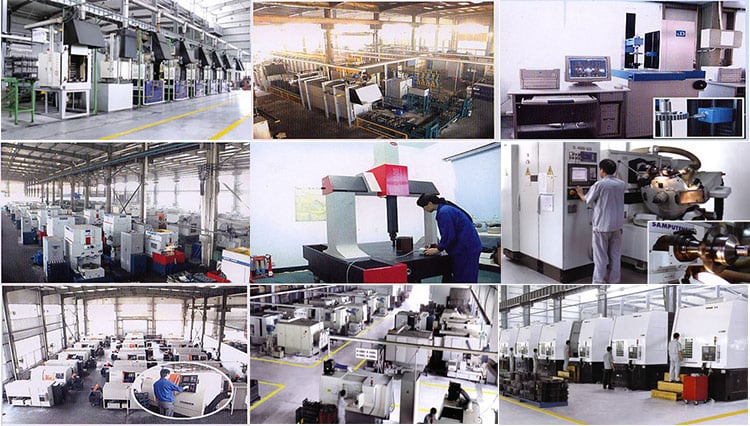
HangZhou EPT Group – one of the largest gearbox producer in China – Electromechanical Services Co. Ltd
HangZhou EPT Group – 1 of the largest gearbox maker in China – Electromechanical Tools Co., Ltd.is a gift company integrating improvement, design and style, manufacturing and product sales,Primary promoting goods include reducer motor,water pump,building machinery and parts,bearings,components and electrical equipment,plastic goods,Labour defense equipment.Our firm always adhere to the operation notion which consists of individuals-oriented, innovation as the soul,be ready for ….
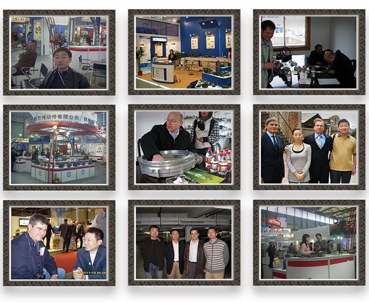
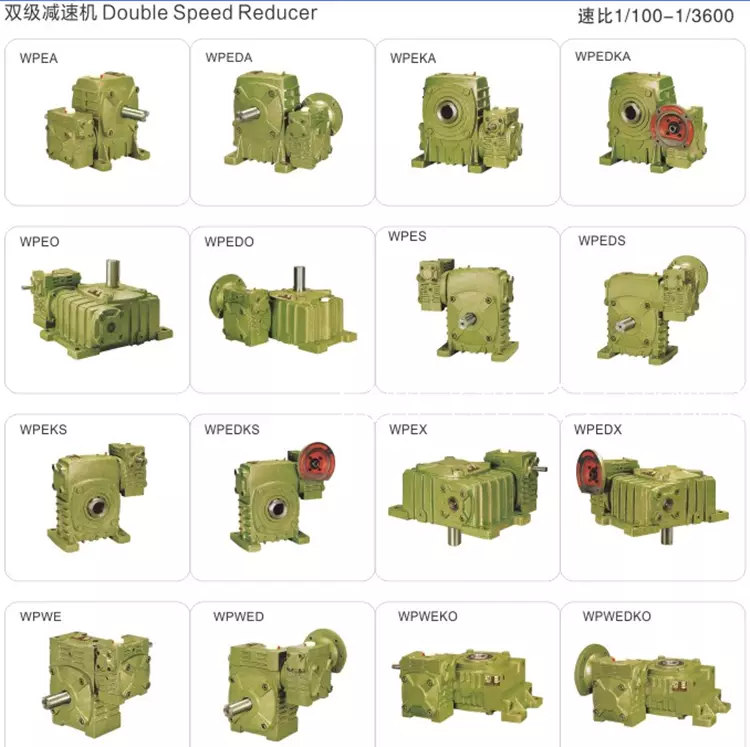
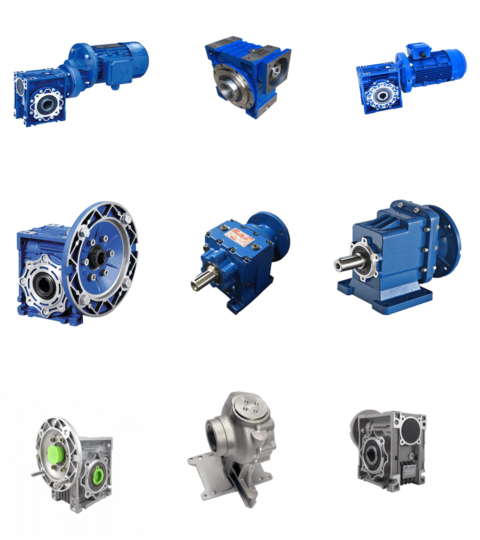
Application spot
Certifications
Revenue territory
Packing & Shipping and delivery
|
Packaging |
|
|
Size |
500 (L) * five hundred (W) * four hundred (D) |
|
Bodyweight |
1.2 T |
|
Packaging Information |
The normal package deal is wood box(Size: L*W*H). If export to european nations around the world,the wood box will be fumigated.If container is too tigher,we will use pe movie for packing or pack it in accordance to clients particular ask for. |
|
Packaging |
|
|
Dimensions |
five hundred (L) * 500 (W) * 400 (D) |
|
Bodyweight |
1.2 T |
|
Packaging Specifics |
The regular package deal is wood box(Size: L*W*H). If export to european countries,the picket box will be fumigated.If container is also tigher,we will use pe movie for packing or pack it in accordance to consumers special request. |
FAQ
Q1: Are you investing business or company ?
A: We are a company in ZheJiang China.welcome to our factory to have a visit.
Q2: How we decide on designs and specifications?
A:You can electronic mail us the series identify & code (for illustration: WJ collection worm gearbox) as nicely as requirement specifics, this kind of as motor power, output pace or ratio, services issue or your application…as considerably information as possible. If you can supply some pictures or drawings, it is better.
Q3: How is your cost? Can you provide any price reduction?
A: We will give the best price tag we can base on your requirements and the quA power just take-off or power takeoff (PTO) is any of a number of methods for getting energy from a energy source, this sort of as a managing motor, and transmitting it to an software such as an hooked up employ or individual device.antities.
This fall: How lengthy ought to I wait around for the opinions soon after I ship the enquiry?
A: Inside of twelve hours.
Q5: What is your product guarantee interval?
A:We offer 1 12 months warranty considering that the vessel departure day remaining China.
Q6: What industries are your gearboxes getting used?
A:Our gearboxes are broadly used to metallurgical equipment, mining products, automation tools, food machinery, packaging gear, tobacco equipment and so on.
Get in touch with us
Cell: +86-13083988828 we chat # or 0086-571-88220971 (WeChat)
E-mail:hzptcorp (a) gmail.com
Fox:+86-571-88220972
Include:No.789 ShenHua Road, , XiHu District, HangZhou, ZheJiang, China
HangZhou EPT Team – one of the most significant gearbox manufacturer in China – Electromechanical Facilities Co. Ltd.


